eTrice Models and Their Relations
eTrice comprises several models:
the ROOM model (*.room) – defines model classes and the logical structure of the model
the Config model (*.config) – defines configuration values for attributes
the Physical model (*.etphys) – defines the structure and properties of the physical system
the Mapping model (*.etmap) – defines a mapping from logical elements to physical elements
In the following diagram the models and their relations are depicted. The meaning of the arrows is: uses/references.
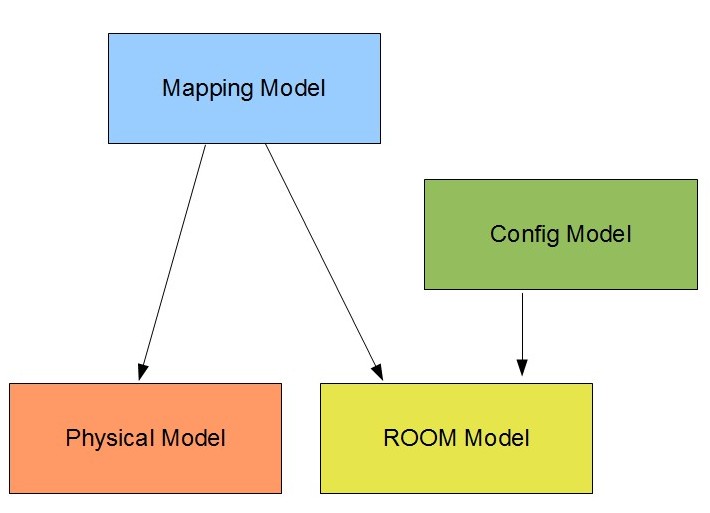
In the following sections we will describe those models with emphasis of their cross relations.
The ROOM Model
The ROOM model defines DataClasses, ProtocolClasses, ActorClasses, SubSystemClasses and LogicalSystems. Thereby the three latter form a hierarchy. The LogicalSystem is the top level element of the structure. It contains references to SubSystemClass elements. The SubSystemClass in turn contains references to ActorClass elements which again contain (recursively) references to ActorClass elements. The complete structural hierarchy implies a tree which has the LogicalSystem as root and where each reference stands for a new node with possibly further branches.
Let’s consider a simple example. It doesn’t implement anything meaningful and completely omits behavioral and other aspects.
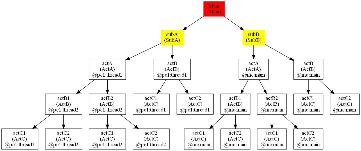
When a LogicalSystem is instantiated then recursively all of the contained referenced elements are instantiated as instances of the corresponding class. Thus the instance tree of the above example looks like in figure below (the third line in the white boxes shows some mapping information, see MappingModel ):
The Config Model
Once we have the ROOM class model we can configure values using the Config model. This can be done on the class level and/or on the instance level. Values defined for class attributes are used for all instances unless there is an instance value configured for the same attribute.
The Physical Model
The physical model defines the physical resources onto which the logical system will be deployed. It is possible to define runtime classes which (currently) only define the overall execution model of the platform.
The PhysicalSystem is composed of NodeReferences which are instances of NodeClasses. Each NodeClass is referencing a RuntimeClass and is defining Threads.
The Mapping Model
The last model finally combines all this information by mapping logical to physical entities.
The result of the mapping is also depicted in above instance tree diagram of the instances. All actor instances (the white boxes) are mapped to a node and a thread running on this node (shown as @node : thread).