Debugging
When the output does not look correct, the generator also provides tools for analyzing such problems. This section starts with a global description of how a railroad diagram is computed and painted, followed by an explanation of how to relate errors in the image to problems in the code.
Global internal structure of the generator
Generating a rail diagram picture starts by reading the .rr input diagram file and converting it to a tree of nodes. There are elementary nodes such as an empty node, a node with a name for terminals, meta-terminals and non-terminals, and the bracketed reference name node. There are also container nodes, the sequence node, the choice node, and the loop node. They combine and organize their child nodes, leading to paths from begin to end in the diagram, stored as a tree of nodes. The root node is a diagram node that contains the name of the diagram and a sequence of rules in the diagram.
The second step is to convert nodes in the tree to elements in a bottom-up traversal through the nodes. An element is a rectangular area in the picture that completely displays that node and all its children. An element also has a horizontal connector for linking it with other elements. Inside an element a collection of graphics (text, quarter arcs, and lines) is created to visualize the flow through the element from the connector at one side to the connector at the other side. Non-leaf nodes also incorporate the elements of their children. Finally, the element and its contents is given a size and relative position. At the parent level the element can thus be seen as a black box with known size and connection points.
Assigning size and relative positions to content in an element is not a trivial process. Usually several graphics are used in a single node. Choice and loop nodes even have multiple independent chains of graphics that connect again at the extremes of the element. To avoid complex computations in assigning sizes and positions, the generator instead introduces variables for positions and sets equality constraints a + val = b (position a is exactly val units away from position b) and/or less-equal constraints a + val ⇐ b (position a is at least val units away from position b). A solver computes values for all the variables using the constraints and derives positions (and thus also sizes) for the element and its content.
At the end of the second step it is known how large the diagram should be. The third step is then to create an image of the appropriate size and traverse the tree again, painting all graphics onto the image. Once that is done, the image is written to the file system, and the job is done.
Analyzing output
Hopefully it will not happen, but you may get output like the following diagram:

By resizing the image the problems are easier to spot:
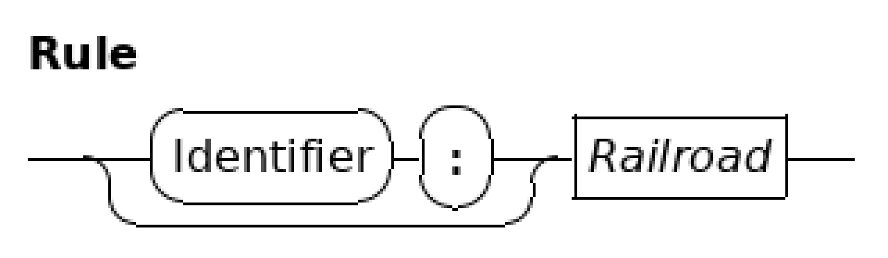
Obviously something is not right here as various lines and arcs are not connected properly to each other. Unfortunately, what the cause for these misalignments is doesn’t become clear. For example, the arc at the left is clearly above the line it should connect to, but is the arc too high or the line too low? To decide where the cause of the problem lies, you need to do some analysis first.
The generator can produce output about how it derives its positions in a diagram. This is controlled by a number of debug-properties in the properties file. The debug.structure property gives the high level element structure, showing how the diagram is built. To understand what an element draws where, the debug.abs_coordinates property is useful in particular when you need to relate positions with other elements. Printed positions in the output should also be the position in the image of the elements if you start counting at (0, 0) for the top-left pixel in the image where positive X axis is to the right and positive Y axis is down. This approach generally finds the element where it goes wrong, and from there it is relatively easy to find the code that generates the element, the variables and the constraints.
There is however a level beyond linking positions in the image to element positions. The printed positions from the debug properties say where the generator believes that a graphic should be. That does not mean painted pixels in the image of that element also actually always end up at the right spot. In other words, the painting code could be wrong too and paint pixels outside its element, omit some pixels, or paint some pixels twice. Visual inspection of the result may not always show that information. To fight this problem, the generator also has a --format=dbg-images option value. It also produces rail diagram images, but instead of a pretty diagram it shows position and painting information. After enlarging it looks like:
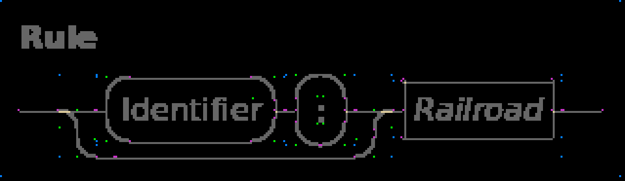
Background is black, and any pixel in the diagram that is different from the background is grey or yellow. The arcs and text thus look very fat since they have a lot of anti-aliasing pixels to smooth their edges.
The grey is mostly not very interesting as long as they are at the expected spot, those pixels are painted once and that is also what you would expect. Yellow pixels are painted more than once. Light yellow pixels that you see are painted twice, there are also a darker yellow colours for indicating touching the same pixel even more often.
Some yellow exists by design, when an arc diverts or merges with a line, some overlap exists to simplify drawing the image. The picture however also has other yellow pixels at the right side of the name boxes. The latter should not be there, as graphics should not overlap except when connecting an arc to a line. These pixels mean that either the horizontal line is one pixel too much to the left or the vertical line is one pixel too far to the right.
To decide what is wrong you need to check graphic positions. The other colours give much of that information. Pink pixels indicate where the computed graphics expect connections by another graphic. For example, the two pink pixels at the top of the Identifier box are from the arcs. They expect the horizontal line to connect there, but in reality the line is painted one pixel below that position. You see the same pattern happen at other horizontal lines as well. The conclusion here is thus that the painting code of a horizontal line is painting one row too low.
In a correctly painted image there should not be pink pixels except at the far left and far right of leading and trailing lines and around the square box of a non-terminal. (The reason for these exceptions is that normal horizontal and vertical lines are used there, but they don’t know there is no other graphic connected there.) Those pink pixels should still properly be aligned with the line though.
The green pixels in the image show the center point of the arc (at the corner of the green pixel furthest away from the arc) as well as the opposite corner, thus allowing checking that the arc pixels do not exceed their box.
Last but not least, the blue pixels show the corners of sub-elements as listed in the debug.structure output. It simplifies finding bounding box positions. In this image those pixels show a problem with the outermost diagram element. At the top-left corner of the image the pixel is at the very edge of the image while at the bottom-right there are black pixels around it. The latter shouldn’t happen, so it points to a bug where the image size is not computed properly.