Getting Started without Operating System
Within this tutorial you will perform the following steps:
- create a DAVE CE™ basic model
- run the New Set of eTrice Models wizard
- create a simple blinky model
- generate, build and run the application
- optionally extend the blinky state machine and create a button controller to switch blinky on and off
Step 1:
As a starting point you should create a DAVE CE™ project for the target HW. Let's call the project BlinkyTutorial_RelaxKit4700_ST, where ST stands for Single Threaded. The following APPs should be included:
- SYSTIMER
- 2 * DIGITAL_IO configured as outputs for the two LEDs.
- 2 * DIGITAL_IO configured as inputs for the buttons.
Hint: For the basic setup and to reduce the initial effort it is sufficient to create just
- SYSTMIER
- 1 * DIGITAL_IO configured as output for LED1 "LED1_P5_9"
For STEP 5 and following you will need the full set of IO Pins.
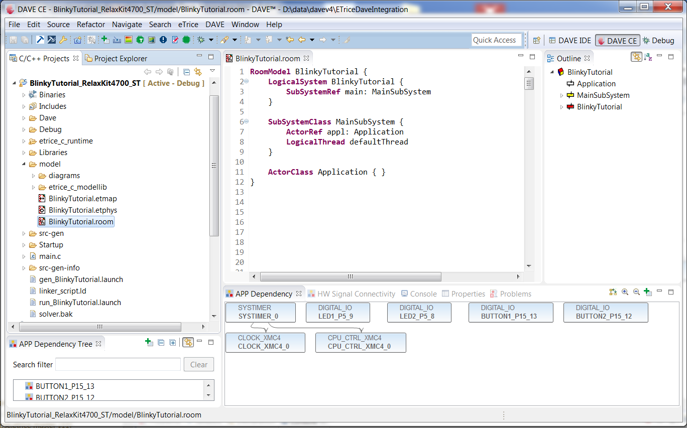
The resulting project should look like this:
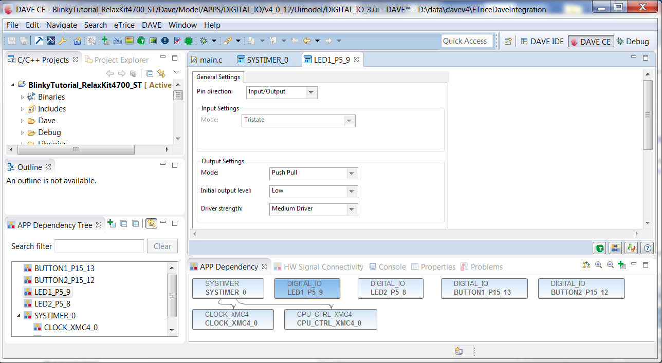
Make sure that the pins are configured correctly. It is a good idea to run it on the real HW to verify that everything is configured correctly. To setup a debug configuration see also Step 4.
Step 2:
Run the *New Set of new eTrice Models" wizard.
To keep an adequate project structure you should create a new folder called model. right click on the project -> new -> other
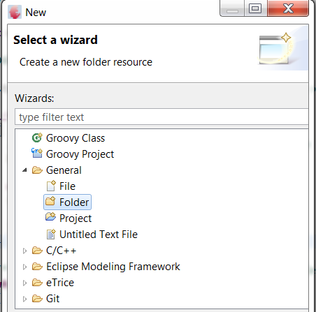
Name the folder model
Run the New Set of eTrice Models" wizard. Right click on the newly created folder -> new -> other Select eTrice/C/New Set of eTrice Models*
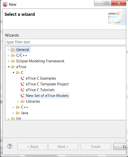
Click Next Name the model BlinkyTutorial
Click Next Enable the check box Copy C-Runtime into project Select ST_XMC_Dave as active platform. Rename the eTrice entry function to etStart.
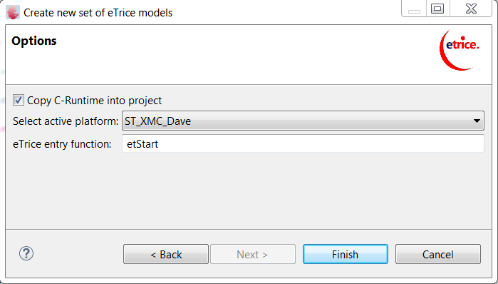
Click Finish
The resulting project should look like this:
The following files/folders should have been created:
- etrice_c_runtime
- etrice_c_modellib within the model folder
- BlinkyTutorial.etmap
- BlinkyTutorial.etphys
- BlinkyTutorial.room
- gen_BlinkyTutorial.launch
- run_BlinkyTutorial.launch
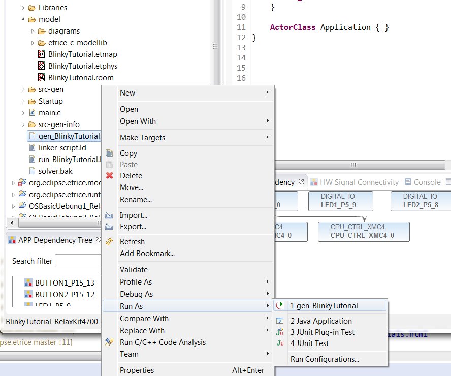
Now you have successfully created your first eTrice model. To complete the step you should generate C-Code out of the model. Right click on gen_BlinkyTutorial.launch -> Run As -> gen_BlinkyTutorial
Make sure that your outline view is activated. Window -> Show View -> Outline.
Once the code is generated you should build the application. After the first build two additional folders are created:
- src-gen
- src-gen-info
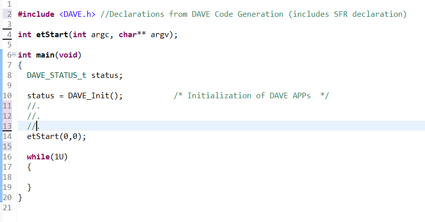
To start the model, you should call etStart from the DAVE™ generated main function.
Step 3:
Now everything is arranged to start modeling with eTrice.
One of the benefits of a modeling language like ROOM is, that it is very easy to build model based libraries either domain specific or for common use. Some common services are part of the eTrice distribution so that we can use it out of the box. The first application we want to create is a blinking LED, therefore we use the eTrice timing service. We just have to import the libraries. Open the BlinkyTutorial.room and add the two import statements:
RoomModel BlinkyTutorial {

    import room.basic.types.* from "etrice_c_modellib/Types.room"

    import room.basic.service.timing.* from "etrice_c_modellib/TimingService.room"

    LogicalSystem BlinkyTutorial {
        SubSystemRef main: MainSubSystem
    }
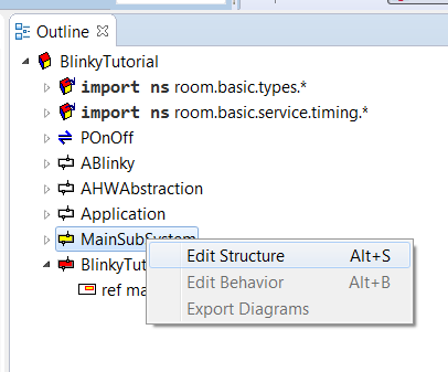
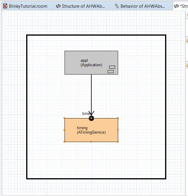
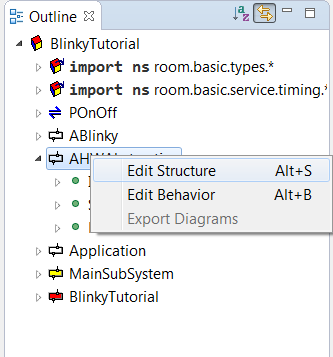
Now we can use the timing service within our application. We just need to connect the application and the service. In the outline view right click the SubSystem and open the structure editor:
Drag and Drop an ActorRef into the subsystem.
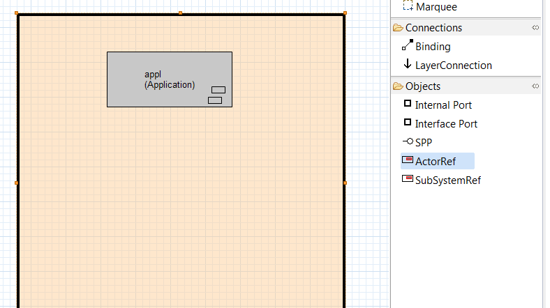
Select the ActorClass ATimingService and name the reference timing.
Draw a connection from application to timing.
Now we can use the timing service inside our application. We will see it later on. Our application should consist of two new actors and a protocol for communication. One actor should represent the HW, the other actor should implement the blinky behavior which is in fact very simple.Creating new elements like actors or protocols are done in the .room file.
Open BlinkyTutorial.room and create a new Actor called AHWAbstraction by adding the following text:
ActorClass AHWAbstraction {
    Structure {
        usercode1 '''
            #include "Dave.h"
        '''
    }
}
Check the outline view to verify that the actor was created.
Create a new protocol class by adding the following:
ProtocolClass POnOff {
    incoming {
        Message on()
        Message off()
    }
    outgoing { }
}
Check the outline view to see that the protocol was created.
The AHWAbstarction should be controlled via the POnOff protocol. That means, whenever we send an on message, the LED should be switched on, whenever we send an off message, the LED should be switched off. Therefore we add an Interface Port from type POnOff to the AHWAbstraction actor. In the outline view right click on AHWAbstraction -> Edit Structure to open the structure editor of the actor.
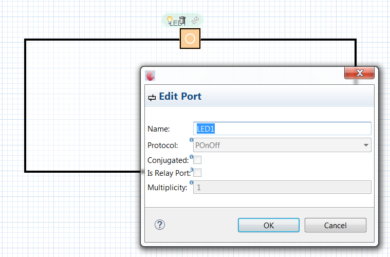
Within the structure editor create a new Interface Port
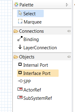
Name the port LED1, the port must be from the newly created protocol type POnOff.
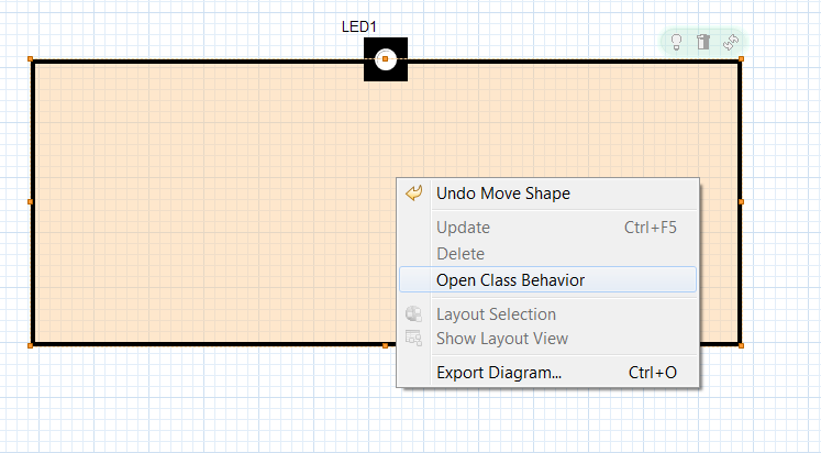
Now we need a state machine which is able to handle the defined messages and to perform the required actions. Create the state machine of the AHWAbstraction actor: Inside the structure editor, right click on the actor. Select Open Class Behavior
The resulting FSM should look like this:
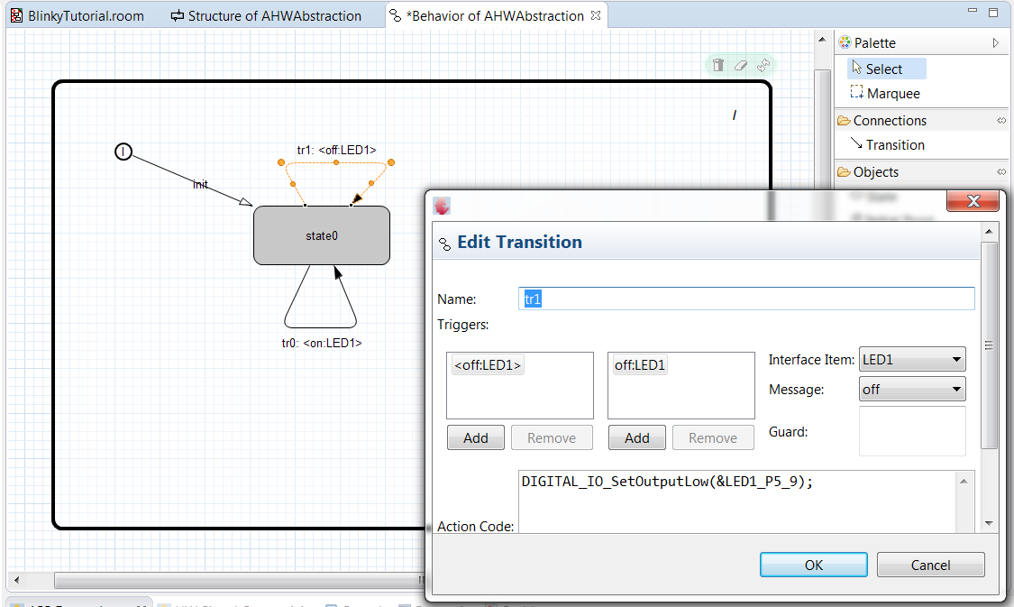
It is just one state with two transitions. Each transition carries one action to switch a digital IO. Here we have the interface to the DAVE™ generated code. The transitions will be triggered from the POnOff protocol.
The resulting textual representation should look like this:
ActorClass AHWAbstraction {
    Interface {
        Port LED1: POnOff
    }
    Structure {
        usercode1 '''
            #include "Dave.h"
        '''
        external Port LED1
    }
    Behavior {
        StateMachine {
            State state0
            Transition init: initial -> state0
            Transition tr0: state0 -> state0 {
                triggers {
                    <on: LED1>
                }
                action '''
                    DIGITAL_IO_SetOutputHigh(&LED1_P5_9);
                '''
            }
            Transition tr1: state0 -> state0 {
                triggers {
                    <off: LED1>
                }
                action '''
                    DIGITAL_IO_SetOutputLow(&LED1_P5_9);
                '''
            }
        }
    }
}
Please notice that the off message switches the LED off and vice versa.
To implement the behavior of the ABlinky actor, we just need to create a new actor, add a port for communication and implement the behavior by adding a state machine with appropriate triggers and actions. Create an ActorClass called ABlinky by adding the following text:
ActorClass ABlinky {
    Structure {
        SAP timer: PTimer
    }
}
Recognize that the structure contains a Service Access Point (SAP) which allows you to use the timing service.
Now, add an additional interface port called out as you did it before and make it a conjugated port. We need to declare the type of the interface (protocol) just once. To define the direction (in or out messages) we need one normal port (AHWAbstraction) and one conjugated port (ABlinky).
To define the behavior, create the following state machine:
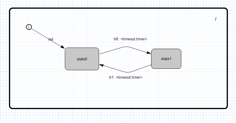
On the initial transition the timer will be started. On the transitions between the states a message on or off will be sent via the out port.
The resulting textual representation looks like this:
ActorClass ABlinky {
    Interface {
        conjugated Port ^out: POnOff
    }
    Structure {
        SAP timer: PTimer
        external Port ^out
    }
    Behavior {
        StateMachine {
            State state0
            State state1
            Transition init: initial -> state0 {
                action '''
                    timer.startTimer(300);
                '''
            }
            Transition tr0: state0 -> state1 {
                triggers {
                    <timeout: timer>
                }
                action '''
                    out.on();
                '''
            }
            Transition tr1: state1 -> state0 {
                triggers {
                    <timeout: timer>
                }
                action '''
                    out.off();
                '''
            }
        }
    }
}
The last step is to build up the application containing the actor classes ABlinky and AHWAbstraction. In the outline view right click to application -> Edit Structure Add ActorRef blinky of ActorClass ABlinky. The same for the AHWAbstraction. Draw the binding between the ports. The resulting system should look like this:

The resulting representation of the complete model should look like this:
RoomModel BlinkyTutorial {

    import room.basic.types.* from "etrice_c_modellib/Types.room"

    import room.basic.service.timing.* from "etrice_c_modellib/TimingService.room"

    LogicalSystem BlinkyTutorial {
        SubSystemRef main: MainSubSystem
    }

    SubSystemClass MainSubSystem {
        ActorRef appl: Application
        LogicalThread defaultThread
        LayerConnection ref appl satisfied_by timing.timer
        ActorRef timing: ATimingService
    }

    ActorClass ABlinky {
        Interface {
            conjugated Port ^out: POnOff
        }
        Structure {
            SAP timer: PTimer
            external Port ^out
        }
        Behavior {
            StateMachine {
                State state0
                State state1
                Transition init: initial -> state0 {
                    action '''
                        timer.startTimer(300);
                    '''
                }
                Transition tr0: state0 -> state1 {
                    triggers {
                        <timeout: timer>
                    }
                    action '''
                        out.on();
                    '''
                }
                Transition tr1: state1 -> state0 {
                    triggers {
                        <timeout: timer>
                    }
                    action '''
                        out.off();
                    '''
                }
            }
        }
    }

    ActorClass AHWAbstraction {
        Interface {
            Port LED1: POnOff
        }
        Structure {
            usercode1 '''
                #include "Dave.h"
            '''
            external Port LED1
        }
        Behavior {
            StateMachine {
                State state0
                Transition init: initial -> state0
                Transition tr0: state0 -> state0 {
                    triggers {
                        <on: LED1>
                    }
                    action '''
                        DIGITAL_IO_SetOutputHigh(&LED1_P5_9);
                    '''
                }
                Transition tr1: state0 -> state0 {
                    triggers {
                        <off: LED1>
                    }
                    action '''
                        DIGITAL_IO_SetOutputLow(&LED1_P5_9);
                    '''
                }
            }
        }
    }

    ProtocolClass POnOff {
        incoming {
            Message on()
            Message off()
        }
        outgoing { }
    }

    ActorClass Application {
        Structure {
            ActorRef hw: AHWAbstraction
            ActorRef blinky: ABlinky
            Binding blinky.^out and hw.LED1
        }
    }
}
The model is finished know. If you missed some steps in between, you also can copy the complete model to your .room file.
Step 4:
Generate, build and run the application.
Generate the application as you did it in step2 (Right click on gen_BlinkyTutorial.launch -> Run As -> gen_BlinkyTutorial). Once the code is generated, you are back in your normal C-Development and you can compile and debug your code as usual. Build the generated code and download it to the target as you normally do it.
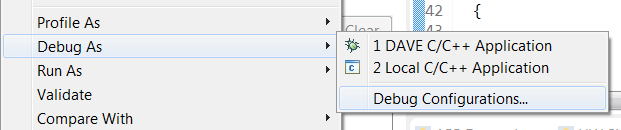
Right click on the project -> Build Project Right click on the project -> Debug As -> DAVE C/C++ Application
The LED1 should blink in a 300ms interval.
Congratulations, you have built you first eTrice Application on top of the Dave™ drivers!!!
Hint: If you start the debugger the first time (for a new project) it might be necessary to setup the debug configuration:
Right click on the project -> Debug As -> Debug Configurations...
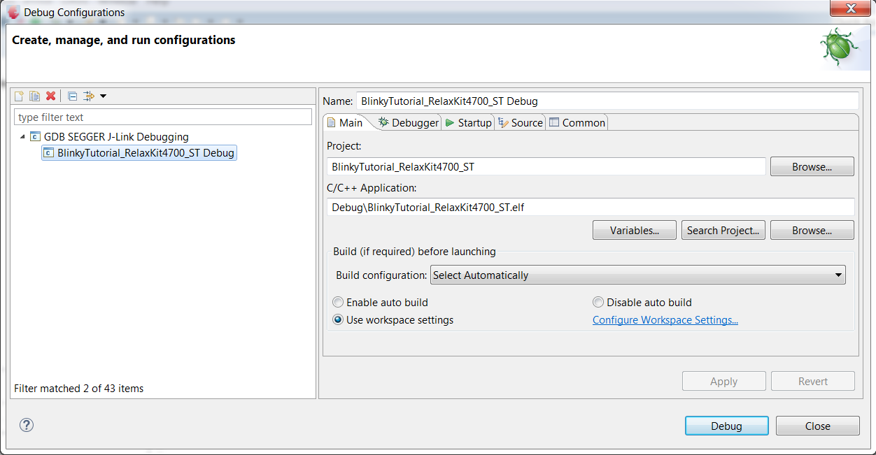
Select the GDB Segger J_link Debugging and press the New button to create a new debug configuration.
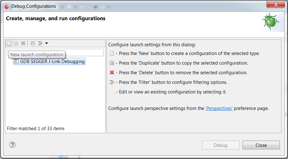
Keep all default settings and press Debug
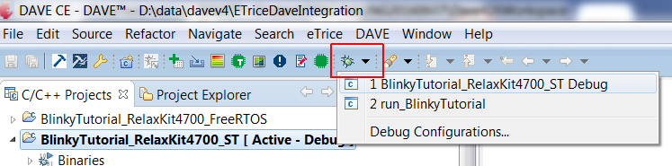
Once the debug configuration is created you can start the debugger either with: Right click on the project -> Debug As -> DAVE C/C++ Application or via the Debug Button:
Step 5:
As further exercise you can extend the model in the following way:
- add a control port to ABlinky from type POnOff
- extend the behavior so that you can switch off and on the blink light
- create a button controller, that recognizes button presses
- do it for both buttons and LEDs
- put everything together to create the complete application
There are many solutions. Here is one of the possible solutions:
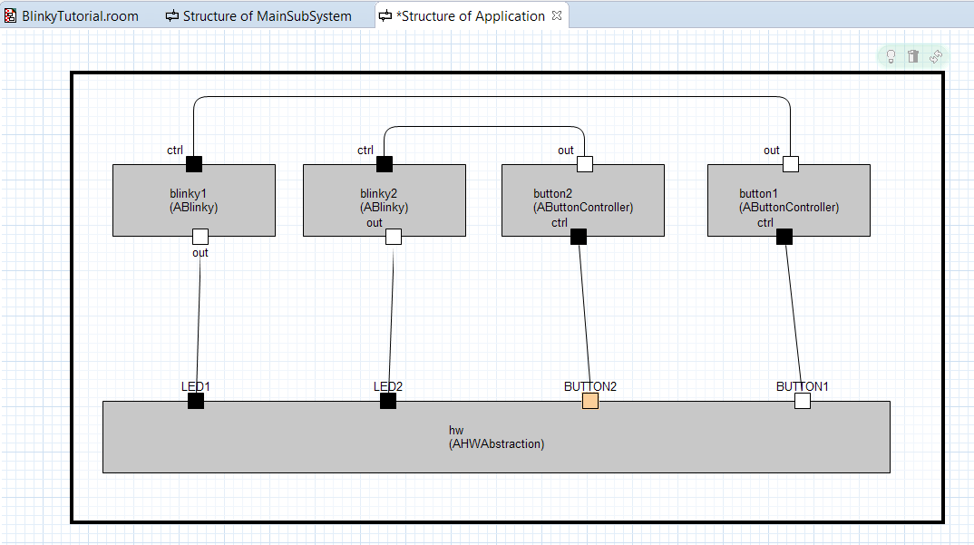
and the complete textual model:
RoomModel BlinkyTutorial {

    import room.basic.types.* from "etrice_c_modellib/Types.room"

    import room.basic.service.timing.* from "etrice_c_modellib/TimingService.room"

    LogicalSystem BlinkyTutorial {
        SubSystemRef main: MainSubSystem
    }

    SubSystemClass MainSubSystem {
        ActorRef appl: Application
        LogicalThread defaultThread
        LayerConnection ref appl satisfied_by timing.timer
        ActorRef timing: ATimingService
    }

    ActorClass ABlinky {
        Interface {
            conjugated Port ^out: POnOff
            Port ctrl: POnOff
        }
        Structure {
            SAP timer: PTimer
            external Port ^out
        external Port ctrl
        }
        Behavior {
            StateMachine {
                State off

                State blinking {
                    subgraph {
                        State on {
                            entry '''
                                out.on();
                            '''
                        }
                        State off {
                            entry '''
                                out.off();
                            '''
                        }
                        EntryPoint tp0
                        Transition tr0: on -> off {
                            triggers {
                                <timeout: timer>
                            }
                        }
                        Transition tr1: off -> on {
                            triggers {
                                <timeout: timer>
                            }
                        }
                        Transition tr2: my tp0 -> on {
                            action '''
                                timer.startTimer(300);
                            '''
                        }
                    }
                }
                Transition init: initial -> off {
                    }

                Transition tr0: off -> tp0 of blinking {
                    triggers {
                        <on: ctrl>
                    }
                }
            Transition tr1: blinking -> off {
                    triggers {
                        <off: ctrl>
                    }
                    action '''
                        timer.kill();
                        out.off();
                    '''
                }
            }
        }
    }

    ActorClass AHWAbstraction {
        Interface {
            Port LED1: POnOff
            Port LED2: POnOff
            conjugated Port BUTTON1: POnOff
            conjugated Port BUTTON2: POnOff
        }
        Structure {
            usercode1 '''
                #include "Dave.h"
            '''
            SAP timer: PTimer
            external Port LED1
            external Port LED2
            external Port BUTTON1
            external Port BUTTON2
            Attribute b1Status: int8
            Attribute b2Status: int8
        }
        Behavior {
            StateMachine {
                State state0
                Transition init: initial -> state0 {
                    action '''
                        timer.startTimer(50);
                    '''
                }
                Transition tr0: state0 -> state0 {
                    triggers {
                        <on: LED1>
                    }
                    action '''
                        DIGITAL_IO_SetOutputHigh(&LED1_P5_9);
                    '''
                }
                Transition tr1: state0 -> state0 {
                    triggers {
                        <off: LED1>
                    }
                    action '''
                        DIGITAL_IO_SetOutputLow(&LED1_P5_9);
                    '''
                }
                Transition tr2: state0 -> state0 {
                    triggers {
                        <on: LED2>
                    }
                    action '''
                        DIGITAL_IO_SetOutputHigh(&LED2_P5_8);
                    '''
                }
                Transition tr3: state0 -> state0 {
                    triggers {
                        <off: LED2>
                    }
                    action '''
                        DIGITAL_IO_SetOutputLow(&LED2_P5_8);
                    '''
                }
                Transition tr4: state0 -> state0 {
                    triggers {
                        <timeout: timer>
                    }
                    action '''
                        if (DIGITAL_IO_GetInput(&BUTTON1_P15_13) == 0) {
                            if (b1Status == 0) {
                                // input changed
                                b1Status = 1;
                                BUTTON1.on();
                            }
                        }
                        else {
                            if (b1Status == 1) {
                                // input changed
                                b1Status = 0;
                                BUTTON1.off();
                            }
                        }

                        if (DIGITAL_IO_GetInput(&BUTTON2_P15_12) == 0) {
                                if (b2Status == 0){
                                // input changed
                                b2Status = 1;
                                BUTTON2.on();
                            }
                        }
                        else {
                            if (b2Status == 1) {
                                // input changed
                                b2Status = 0;
                                BUTTON2.off();
                            }
                        }
                    '''
                }
            }
        }
    }

    ProtocolClass POnOff {
        incoming {
            Message on()
            Message off()
        }
        outgoing { }
    }
    ActorClass AButtonController {
        Interface {
            Port ctrl: POnOff
            conjugated Port ^out: POnOff
        }
        Structure {
            external Port ctrl
            external Port ^out
        }
    Behavior {
            StateMachine {
                State off
                State on
                Transition init: initial -> off
                Transition tr0: off -> on {
                    triggers {
                        <on: ctrl>
                    }
                    action '''
                        out.on();
                    '''
                }
                Transition tr1: on -> off {
                    triggers {
                        <on: ctrl>
                    }
                    action '''
                        out.off();
                    '''
                }
            }
        }
    }
    ActorClass Application {
        Structure {
            ActorRef hw: AHWAbstraction
            ActorRef blinky1: ABlinky
            Binding blinky1.^out and hw.LED1
        Binding blinky2.^out and hw.LED2
            ActorRef blinky2: ABlinky
        Binding hw.BUTTON1 and button1.ctrl
            Binding button2.ctrl and hw.BUTTON2
            Binding button2.^out and blinky2.ctrl
            Binding blinky1.ctrl and button1.^out
            ActorRef button1: AButtonController
            ActorRef button2: AButtonController
        }
    }

}
In the tutorial we used the Systimer APP as timing base for the model. It is also possible to run the model without the Systimer APP. Please open etrice-c-runtime/src/platforms/ST_XMC_Dave/etPlatform.h. To work without Systimer APP you just need to undef ET_USE_DAVE_SYSTIMER_APP. In this case you have to remove the Systimer APP from the Dave™ model.