-
CHESS Profile
The CHESS UML profile:
- restricts the set of MARTE, SysML and UML entities that can be created in the CHESS model,
- provides the set of stereotypes required to enable the user to work with the CHESS component model,
- provides some MARTE stereotypes extensions to allow the specification of computation-independent real-time properties,
- defines a new set of stereotypes for the support of dependability modeling and contract-based design.
CHESS Editor
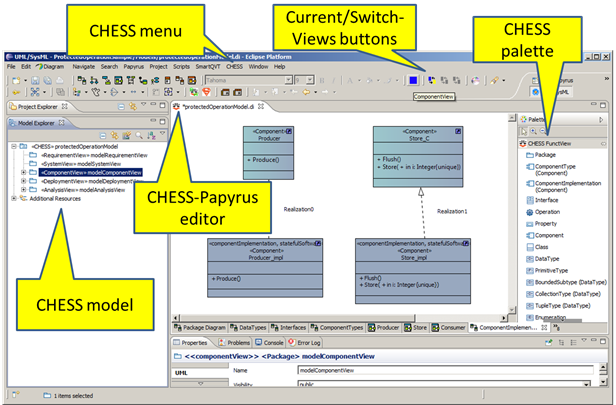
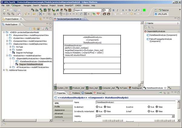
The CHESS editor extends the Papyrus UML editor and is activated when a CHESS model is created or opened (see Figure 1).
A CHESS model is a UML model with the CHESS profile applied to it; creating a CHESS model and applying the CHESS profile can be done using a dedicated wizard.
The CHESS editor allows working with the Papyrus UML by using the CHESS design views. Each design view applies specific constraints on the UML diagrams and entities that can be created, viewed or edited in that view.
The CHESS editor allows switching between views. It also keeps the status of the current view and during the modeling activity prevents the modeler from violating the constraints defined for the current diagram-view pair.
The native Papyrus palettes have been customized in order to show only the entities that are allowed to be created in the current diagram view.
CHESS Views
The views defined in CHESS are the requirement, system, component, deployment and analysis views.
The requirement view is used to model requirements by using the standard requirement diagram from SysML.
The system view is used to model system entities by using SysML; it is an ongoing development that has been recently introduced in CHESS in order to support the system to software co-engineering phase.
The component view is used to model CHESS software components (also called the PIM model): is actually composed by two sub-views, the functional and the extra-functional ones, according to the CHESS separation of concerns principle.
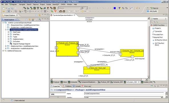
The functional view allows the functional specification of the CHESS components (see Figure 1 and Figure 2).
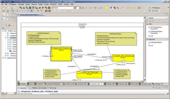
Figure 1: Component View - Functional View - Component TypesFigure 2: Component View - Functional View - Component InstancesThe extra functional view (see Figure 3) allows the specification of real time properties like periodic and sporadic activation patterns, worst-case execution time and deadline. Regarding dependability it supports the specification of error models (i.e. fault-error-failure chains) for software and offers the possibility for the user to specify probabilistic values related to fault occurrence and failure propagation between components.
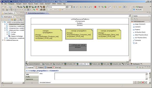
Figure 3: Component View - Extra Functional View - Component InstancesThe deployment view (Figure 4) is used to describe the hardware platform where the software runs (i.e. CPUs, buses) and software to hardware components allocation. Dependability properties can be provided for the hardware as for the software components. Moreover failures propagation from hardware to software can be specified.
Figure 4: Deployment View - HW Component instance and SW allocationThe analysis view (Figure 5) is used to provide information needed to run the specific analysis; in particular it is currently useful to set the information about the dependability measure of interest (i.e. reliability or availability) that needs to be evaluated.
Figure 5: Analysis ViewContract-based design
The contract-based design enriches the system architecture model with expressions asserting the expected properties of the system, its components and environment. In order to allow compositional reasoning, the property of a component are restricted to its interface considering the component as a black box (without constraining the internal variables of the component) and are structured into contracts, pairs of properties representing an assumption and a guarantee of the component: an assumption is an assertion on the behaviour of the component environment, while a guarantee is an assertion on the behaviour of the component provided that the entire set of assumptions holds.
The contract specification can further be enriched by categorising contracts into strong and weak to allow for better support for specification of reusable components behaviour. Such components are intended to work in different environments, and often exhibit environment-specific behaviours and assumptions.
Model validator
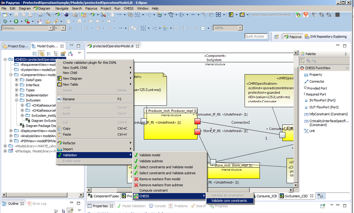
For reasons of practicality, not all the constraints posed by the CHESS methodology on the model formalisms and contents can be enforced on the fly during user modeling; some of them must be checked in a batch mode. To this end the CHESS editor extends the standard UML model validator which ad-hoc checks that the user model conforms with the constraints imposed by the CHESS methodology, for example the well-formedness of entities, attributes, relations.
Figure 6: Invoking CHESS model validatorModel transformations
CHESS supports model-based analysis of the systems for schedulability, dependability, as well as code generation from model. Both features are implemented through model transformations which are invoked through the CHESS editor menu.
Dependability analysis currently supported are:
- failure propagation analysis,
- state-based quantitative analysis.
Schedulability Analysis and Ada 2005 Code Generation
Schedulability analysis allows the calculation of the worst case response time for each declared periodic or sporadic activity. The analysis results are back propagated to the proper PIM components, also a summary report is provided to the user (see Figure 7). The intent of the back-propagation feature is that the user need not be concerned with the specifics of the analysis tool and need not learn its input and output formats: back-propagation decorates the user model with the relevant information that results from the analysis in full transparency from the analysis engine and its actual operation.
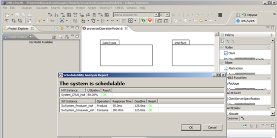 Figure 7: Schedulability Analysis Report
The real-time properties of interest like period, offset and minimal inter-arrival time are specified in the model through a dedicated declarative language defined in the CHESS profile. The aforementioned properties are then automatically applied to the model implementation through model transformation in accord with the computational model chosen by the user. At the present time, CHESS supports the Ravenscar Computational Model [1] which meets the requirements of a large spectrum of real-time application domains. The generated implementation (called the PSM, for platform-specific model) is then given in input to the schedulability analysis and it also used during the code generation phase:
The preservation of other real-time properties related to the execution time like WCET and deadline is also enforced in the generated code through dedicated checks by using specific API of the target run-time environment (this feature is an on-going development).
This approach guarantees the preservation of the real-time properties statically assumed in the PIM and PSM models, and verified by the analysis down to the code.
The schedulability analysis is performed by using an adaptation of the third-party MAST tool developed and distributed by the University of Cantabria [2].
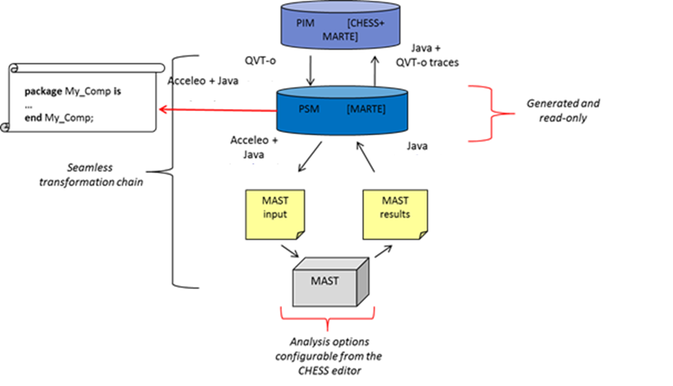
Regarding the transformation chain (Figure 8), first the CHESS PIM is transformed into the PSM model by using QVT-o. Then the PSM is transformed into the MAST input by using Acceleo and Java. Regarding the back propagation, Java is used first to load the MAST results into the PSM, then QVT-o traces are used to propagate the results back to the PIM model.
Figure 8: Transformation chain[1]A. Burns, B. Dobbing, T. Vardanega. Guide to the Use of the Ada Ravenscar Profile in High Integrity Systems. Technical Report YCS-2003-348. University of York (UK), 2003. Available at http://www.sigada.org/ada_letters/jun2004/ravenscar_article.pdf.
[2]Universidad de Cantabria. Mast: Modeling and Analysis Suite for Real-Time Applications. http://mast.unican.es/System Design
System Definition
Requirements Specification
Requirements can be represented in the model by using the SysML standard support, i.e. by using the Requirements Diagram and Requirement SysML construct. CHESS comes with a dedicated view/package called “RequirementView”, where the SysML Requirement Diagram and then the requirements can be created. Requirements available in the CHESS model can then be linked to other architectural entities by using the standard SysML support, so in particular by allocating requirements to components using the Satisfy relationships.
System Component Definition
During this activity, the architecture of the system, i.e. its constituent components and their relationships, is produced. The definition of the system architecture foresees the design of components in isolation, i.e. components designed out of any particular context (to exploit their reuse), or the identification (reuse) of the components from existing libraries/models. The hierarchical modelling of the entire system architecture is supported to be able to manage the complexity of the system itself, where the hierarchy can be obtained by using a top-down or bottom-up design process, where the later in particular can be realized by following a design by reuse approach.
A component must come with typed input/output ports representing the boundary of the component itself, where ports represent interaction points through which the component can exchange information with the context. It is worth noting that the modelling of the component boundary cannot be limited to the identification of the input/output ports of the component itself; additional information about the possible (functional and extra-functional) behaviours of the component and the expected behaviours of the context must be provided, e.g. to be able to evaluate if a given component can collaborate in a given scenario. This relevant part of the specification of the component boundary can be performed by using the contract-based approach. When a component has been defined, then it can be instantiated as part of the given system under design and connected to the other instances already identified.
The system is modelled, i.e. it is decomposed, as a collaboration of instances of components. The decomposition of the architecture can proceed at any level, i.e. a system component can be also decomposed, according to its complexity. Different instances of the same component (and different ports with the same type) can be represented as a single instance with multiplicity greater than 1. SysML, the OMG general-purpose modelling language for systems engineering, is proposed in CHESS for the modelling of the system and its constituent components. In particular, SysML Block Definition Diagram is used to model the system and its components, while a SysML Internal Block Diagram can be associated to the system or component and used to model its input/output ports, its decomposition into parts and how the parts are connected.
Requirements Formalization
This activity has the goal of translating the informal requirements allocated to system components into formal properties. Formal properties are textual expressions specified in a restricted grammar so that their semantics is formally defined (in rigorous mathematical terms). Such expressions refer to the elements of the system component interface defined in the previous activity. CHESS supports the specification of well-formed formal properties with the help of an automated completion feature that suggests the possible continuations of a partial specification. Formal properties can be further structured into contracts.
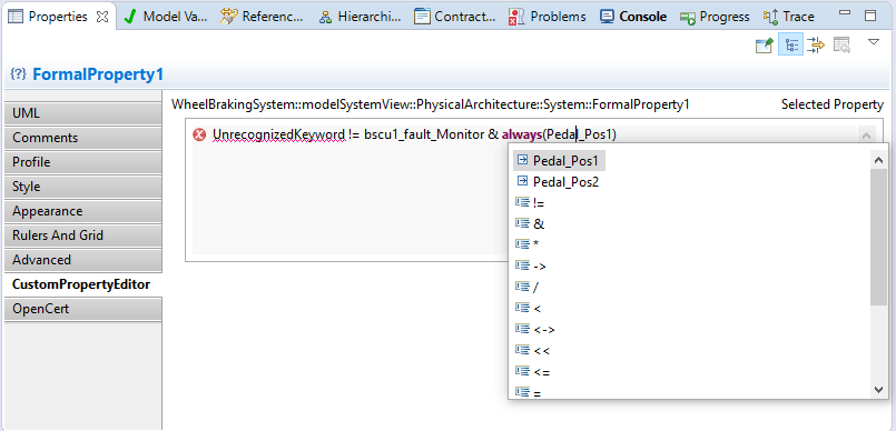 Property Editor with “completion assistance”
Requirements Early Validation
This validation is done by checking if a specific guarantee of the contract satisfies the assumption of another contract.
Functional Refinement
The architectural refinement defines in detail how the different parts of the system are connected and interact to fulfill the system requirements. To refine the architecture, the sub-requirements and sub-components of the system must be identified. Allocation of requirements/sub-requirements to sub-components must be managed, as well as formalization of sub-requirements. In case of reuse of components (as sub-components), associated satisfied requirements and implemented contracts are reused. Information about requirements refinement can be managed in CHESS by using the SysML standard support.
Parameters and Configurations
The parameterization of an architecture is the procedure to define and use a (possibly infinite) set of parameters to set the number of components, the number of ports, the connections, and the static attributes of components. The instantiation of an architecture is the procedure to assign the values of the parameters used in the input parameterized architecture. The outcome is an architecture with a fixed number of components, ports, connections, and static attributes of components.
Contract Refinement
The contract refinement requires one prior phase, the definition of the contract. Contracts refinement must follow the requirements refinement. Indeed, a contract is implicitly linked to the formalized requirements (via its assumption and guarantee properties); so, the requirements referred by contracts appearing in a refinement relationship should also have a corresponding refinement traced.
Component’s Nominal and Faulty Behaviour Definition
System component static definition, i.e. its properties, ports, contracts, can be enriched with behavioural models by means of UML state machine diagrams. In CHESS, state machine diagrams can be used to model the nominal and the faulty behaviour of the component. Nominal state machine are basically standard UML ones. In CHESS, by using a subset of the UML support for state machine modelling, it is also possible to use model transformation to automatically generate an SMV (the input language of nuXmv) representation of the modelled nominal state machines, together with the components structure definition (this is then used to perform automatic generation of fault tree. In nominal state machines, each transition comes with a guard and an effect. The guard is a boolean condition upon the values of components properties. The effect must be expressed by using the SMV language, to model component properties assignment.
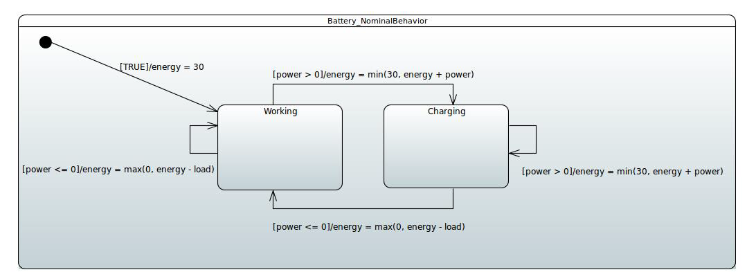 Example of nominal state machine (using SMV as action language)
The behavioural model of the component can be enriched with the faulty behaviour. Faulty behaviour is modelled in CHESS by using the dedicated dependability profile. The CHESS dependability profile enables dependability architects to model dependability information necessary to conduct dependability analysis, basically by allowing the modelling of failure modes and criticality, the failure behaviours for a component in isolation (so how events can lead to components failure modes) and the failure modes propagation between connected components (via components ports).
Functional Early Verification
Contract-Based Verification of Refinement
If assumptions and guarantees are formal properties, which means they are specified in a formal language such as some specific kind of temporal logic, the architectural decomposition can be verified by checking that the contract refinement is correct: this consists of checking that, for all composite components, the contract of the composite component is ensured by the contracts of the subcomponents –considering their interconnection as described by the architecture -and that the assumption of each subcomponent is ensured by the contracts of the other sibling subcomponents and the assumption of the composite component.
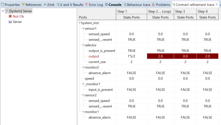 An example of the result of the check contract refinement shown in the Trace View. In this case, it is possible to see that one refinement is failed, and the counter example.
Contract-based Verification of Refinement for Strong and Weak Contracts
Strong and weak contracts are introduced to support out-of-context reasoning and component reuse across variety of environments. While strong contracts must hold in all environments, the weak ones are environment-specific. Prior to performing the refinement check using strong and weak contracts, contracts must be created and allocated to the component types, which represent out-of-context components. At the component type level, the user indicates if a contract is strong or weak. When the component type is instantiated in a particular system to a component instance, all the strong, and a subset of weak contracts can be identified as relevant in the particular system in which the component is instantiated. Identifying which are those relevant weak contracts can be done manually on the component instance level.
Contract-Based Verification of State Machines
As a further verification step, CHESS enables to verify whether the behavioural specification of the system, specified by state machines, is compliant with the contract specification.
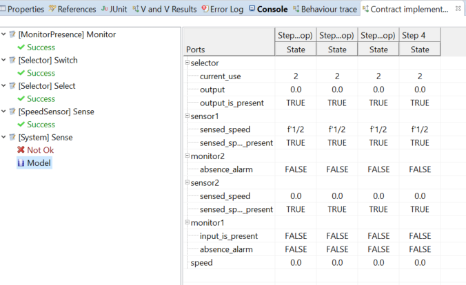
An example of the result of the check contract implementation shown in the “Trace” view. It is possible to see that four contracts are not satisfied by the state machines of their associated component and one contract not.Model Checking
Besides the verification of contracts, the user may want to verify other properties on the state machine. The specifications to be checked on the FSM can be expressed in temporal logics like Computation Tree Logic (CTL), Linear Temporal Logic (LTL) extended with Past Operators, and Property Specification Language (PSL) that includes CTL and LTL with Sequential Extended Regular Expressions (SERE), a variant of classical regular expressions. It is also possible to analyse quantitative characteristics of the FSM by specifying real-time CTL specifications.
CTL and LTL specifications are evaluated by nuXmv to determine their truth or falsity in the FSM. When a specification is discovered to be false, nuXmv constructs and prints a counterexample, i.e. a trace of the FSM that falsifies the property.
There are three possible model checking available:
- check ctlspec: it performs fair CTL model checking. A CTL specification is given as a formula in the temporal logic CTL. A CTL formula is true if it is true in all initial states.
- check invar: it performs model checking of invariants. Invariants are propositional formulas which must hold invariantly in the model.
- check ltlspec: it performs LTL model checking. An LTL formula is true if it is true at the initial time.
Safety Analysis
Model-Based Safety Analysis
Fault injection
The faulty behaviour for a component is provided through a state machine, the latter tagged with the <<ErrorModel>> stereotype defined in the CHESS dependability profile13. In the error model, the information about the error states can be provided by using the <<ErrorState>> stereotype. Then, for a given error state, the effect upon a property of the component, and so the effect on its nominal behaviour, can be also provided by using pre-defined effects:
- StuckAt: models the effect of being stuck at a fixed value.
- StuckAtFixed: models the effect of being stuck at a fixed random value.
- Inverted: models the effect of being stuck at the inverted last value.
- RampDown: models the effect of decreasing the value of a property by a certain value.
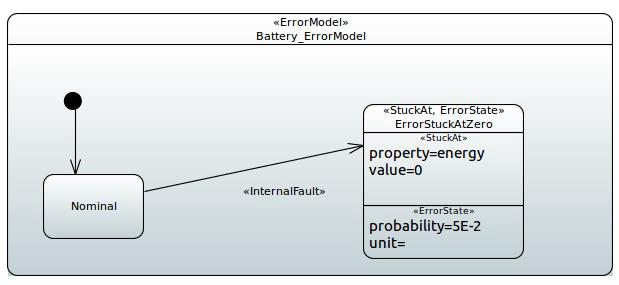 State machine modelling faulty behaviour
Fault-tree generation and FMEA generation
Once the system architecture has been provided, by mean of components definition and their nominal and error models, the fault tree generation can be obtained by invoking the xSAP symbolic model checker through the CHESS environment. Please refer to the CHESS User Manual for instructions on how to configure the analysis.
Once the analysis is executed, the fault tree is automatically shown in a dedicated panel in the frontend. If fault probabilities have been specified during the configuration of the error model, the fault tree will report their combination. The fault tree can be examined, in particular the minimal cut-set and so the basic fault conditions which can led to the top-level failure.
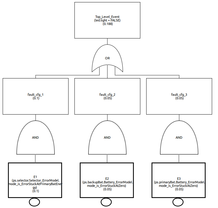 A fault tree visualized in the CHESS Editor View; note the probabilities associated to the top and basic events
Along with the fault-tree generation, it is possible to generate the FMEA table. FMEA analysis is configured in a similar mode as the fault-tree analysis, see the CHESS User Manual for details.
Contract-Based Safety Analysis
The contract-based safety analysis identifies the component failures as the failure of its implementation in satisfying the contract. When the component is composite, its failure can be caused by the failure of one or more subcomponents and/or the failure of the environment in satisfying the assumption. As result, this analysis produces a fault tree in which each intermediate event represents the failure of a component or its environment and is linked to a Boolean combination of other nodes; the top-level event is the failure of the system component, while the basic events are the failures of the leaf components and the failure of the system environment.
Safety Case
In most industries, a well-structured Safety-Case, i.e. a concluding argument that the system to be released for public usage is sufficiently safe, is required by safety standards and certification authorities. Standards mentioning the obligation for a Safety Case include IEC 61508, ISO 26262 and many more. The notion of a Safety Case is not formally defined by the standards and therefore varies among different standards, regions and industry branches – it can even depend on the company who creates it or on the safety assessor or local certification authority. Where this term is in use, it refers at least to a collection of all relevant output documents from the safety process, from which an external assessor can conclude that everything has been done to assure that the product is safe in its practical application.
Document Generation
As part of the evidences to be used at support of the safety case, the tool can generate a document summarizing the modelling of the system components and the verification, validation, and analysis results. The generated document is composed by a list of sections. The first section includes the diagrams that are not associated to a specific component, such as the block definition diagrams.


