Finite State Machines
Description
In ROOM each actor class can implement its behavior using a finite state machine (FSM). Events sent to the end ports of an actor will be forwarded to and processed by the state machine, which can then trigger transitions between states to perform actions. The actor can only be in one state at a time.
Motivation
For event driven systems a finite state machine is ideal for processing the stream of events. Typically during processing new events are produced which are sent to peer actors.
Details
Initial Transition
Let's begin with a straightforward finite state machine that includes just the fundamental elements: a single state and an initial transition.
In this first example, we define an actor class without any external interfaces or structural components, focusing on its behavior.
The state machine starts in the Idle state, after the initial transition.
Transitions and states can contain code blocks.
In this example, when the state machine takes the initial transition it will run the assigned action code.
Entering into the Idle state, the state machine will then run the entry code of that state.
It is also possible to add an exit code block to a state.
Note that in subsequent examples, code blocks will be mostly omitted for brevity.
Since this example only has a single state and one initial transition, it serves as a starting point for more complex state machine examples.
It demonstrates the fundamental structure of a state machine, where a system initializes and enters an initial state, which in this case is Idle.

ActorClass Example_1 {
	Interface {
	}
	Structure {
	}
	Behavior {
		StateMachine {
			State Idle {
				entry '''// action runs when state machine enters this state'''
			}
			Transition init0: initial -> Idle {
				action '''// action runs when state machine executes this transition'''
			}
		}
	}
}
Transition between two states
In this Example, we extend the basic state machine model by introducing an interface to process incoming messages and adding a second state Active and transition tr0 between the two states. The added interface is a port named switch of type PSwitch, over which messages can be sent.
By adding the port and the event-driven transition, this example demonstrates how a system can respond to external stimuli. When the state machine receives a message from the switch port, it will transition from the Idle state to the Active state.

ActorClass Example_2 {
	Interface {
		Port switch: PSwitch
	}
	Structure {
		external Port switch
	}
	Behavior {
		StateMachine {
			State Idle
			Transition init0: initial -> Idle
			State Active
			Transition tr0: Idle -> Active {
				triggers {
					<on: switch>
				}
			}
		}
	}
}
Choice Points
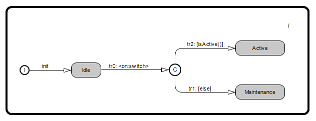
Building upon the concepts introduced in Example_2, the state machine Example_2b introduces the concept of a choice point, which allows for conditional transitions based on a boolean expression. Here's a description focusing on the new concepts:
In Example_2b, the actor class retains the external switch port and adds a new operation isActive(), which determines a conditional transition. The state machine now includes three states: Idle, Active, and Maintenance, with transitions guided by a choice point. When an event on the switch port triggers tr0, the system transitions to the choice point cp0. At cp0, the system evaluates the isActive() operation:
- If
isActive()returnstrue, the system transitions to theActivestate viatr2. - If
isActive()returnsfalse, the system transitions to theMaintenancestate viatr1.
A choice point with multiple conditional paths allows for dynamic state transitions based on evaluated conditions.
ActorClass Example_2b {
	Interface {
		Port switch: PSwitch
	}
	Structure {
		external Port switch
	}
	Behavior {
		Operation isActive(): boolean '''
			// Perform conditional check here
			return false;
		'''
		StateMachine {
			State Idle
			Transition init0: initial -> Idle
			State Active
			Transition tr0: Idle -> cp cp0 {
				triggers {
					<on: switch>
				}
			}
			State Maintenance
			ChoicePoint cp0
			Transition tr1: cp cp0 -> Maintenance
			Transition tr2: cp cp0 -> Active {
				cond '''isActive()'''
			}
		}
	}
}
Hierarchical State Machines
Example_3 introduces the concept of a substate machine within a state.
The system starts in the Idle state. When an event on the switch port triggers tr0, the system transitions from Idle to Active.
Once in the Active state, an inner state machine is activated.
This inner state machine begins with an initial transition to the Calibrating substate.
This example illustrates how to embed a state machine within a state, allowing for more granular control and management of transitions within a complex state.


ActorClass Example_3 {
	Interface {
		Port switch: PSwitch
	}
	Structure {
		external Port switch
	}
	Behavior {
		StateMachine {
			State Idle
			Transition init0: initial -> Idle

			State Active {
				subgraph {
					Transition init: initial -> Calibrating {
					}
					State Calibrating
				}
			}
			Transition tr0: Idle -> Active {
				triggers {
					<on: switch>
				}
			}
		}
	}
}
History in Hierarchical State Machines
The goal of this example is to illustrate the concept of "deep history".
In Example_4, the actor class has two external ports, switch of type PSwitch and sensor of type PSensor. The state machine includes two primary states: Idle and Active, and two substates within Active, namely Calibrating and Operational.
The state machine re-enters the last active state within the innermost substate machine after handling a transition execution. Here's how it works:
- Initial State and Transition:
- The system starts in the
Idlestate. An event on theswitchport triggers the transitiontr0, moving the system to theActivestate.
- The system starts in the
- Substate Machine within Active:
- Upon entering
Active, the substate machine starts with an initial transition to theCalibratingsubstate. Once calibration is complete (triggered by thecalibratedevent on thesensorport), the system transitions to theOperationalsubstate via transitiontr2.
- Upon entering
- Interrupting and Returning to the Substate:
- If the system is in
Operationaland an off event occurs on theswitchport, the system exits theActivestate and transitions back toIdleviatr1. - When the an
onevent occurs again, the state machine transitions back toActive. Due to the deep history mechanism, the state machine goes immediately to theOperationalsubstate because it was the last active substate before exitingActivepreviously.
- If the system is in
By remembering the last active substate in complex states, the system has a mechanism to maintain continuity in its operations and resume where it left off.


ActorClass Example_4 {
	Interface {
		Port switch: PSwitch
		Port sensor: PSensor
	}
	Structure {
		external Port switch
		external Port sensor
	}
	Behavior {
		StateMachine {
			State Idle
			Transition init0: initial -> Idle

			State Active {
				subgraph {
					Transition init: initial -> Calibrating {
					}
					State Calibrating
					State Operational
					Transition tr2: Calibrating -> Operational {
						triggers {
							<calibrated: sensor>
						}
					}
				}
			}
			Transition tr0: Idle -> Active {
				triggers {
					<on: switch>
				}
			}
			Transition tr1: Active -> Idle {
				triggers {
					<off: switch>
				}
			}
		}
	}
}
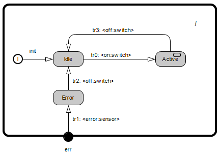
Group Transitions, Transition Points and Event Triggering Precedence Rules
In Example_5, the state machine builds upon previous examples by introducing three key concepts: group transitions, transition points and event triggering precedence.
These concepts help the state machine handle transitions in a well-defined and consistent way, and they allow more control over transitions between different levels in the state hierarchy.
1. Group Transitions:
Group transitions allow a composite state to handle certain events uniformly across all its substates. This means that regardless of which substate is currently active, a specified event will trigger a transition from the composite state itself, effectively acting as an interrupt from a higher level in the hierarchy.
Transition tr3 (Active -> Idle): This is a group transition triggered by an off event on the switch port.
It applies to all substates within Active.
Regardless of whether the system is in Calibrating, Operational, or OperationalError, an off event will trigger an exit from the current substate, an exit from the Active state, and finally a transition to the Idle state.
Note that a group transition does not need to start from the immediate parent of a substate like it is shown in this example - it also applies when the current state is nested multiple levels down.
2. Transition Points:
Transition points can be used when a group transition needs to target a substate.
TransitionPoint err: This transition point is used to manage error transitions globally in the state machine.
When an error event occurs, the state machine transitions via the TransitionPoint to the Error state regardless of whether the current state is Idle or one of the substates of Active, with one notable exception.
There is a special consideration for when the state machine is in the Operational state.
In this case, two transitions have matching triggers for the error event: one on transition tr5 and the other on transition tr1.
The state machine chooses the transition to take based on a set of event triggering precedence rules.
These rules will be explained next.
3. Event Triggering Precedence:
When an event occurs, the state machine searches for a matching trigger in a fixed, consistent order. This ensures that repeated occurrences of the same event in the same state will always trigger the same transition.
- The state machine first searches for a trigger directly from the current state.
- If no trigger is found, it searches for group transitions in the parent state, recursively up the state hierarchy.
- If no triggers are satisfied at any scope level, the event is discarded, and the state remains unchanged.
In this example, we have two transitions triggered by the error event:
- Transition within Active's Subgraph:
Operational->OperationalError - Group Transition: TransitionPoint
err->Error
Here's how the event triggering rules apply:
When an error event occurs, the state machine searches for a matching trigger from the current state.
If the state machine is in the Operational state, it first checks for matching triggers directly from that state.
Since transition tr5 has a trigger matching the error event, this transition is taken.
Conversely, if the state machine is in Calibrating or OperationalError, there are no transitions with matching triggers directly from those states.
The state machine moves on to the parent state to search for matching triggers.
In the Active state, there are also no group transitions with triggers matching the error event, so the state machine continues on to the top-level State.
Here there is a trigger on the group transition tr1 that matches the error event, and the state machine selects this transition.

ActorClass Example_5 {
	Interface {
		Port switch: PSwitch
		Port sensor: PSensor
	}
	Structure {
		external Port switch
		external Port sensor
	}
	Behavior {
		StateMachine {
			State Idle
			Transition init0: initial -> Idle

			State Active {
				subgraph {
					Transition init: initial -> Calibrating {
					}
					State Calibrating
					State Operational
					Transition tr4: Calibrating -> Operational {
						triggers {
							<calibrated: sensor>
						}
					}
					State OperationalError
					Transition tr5: Operational -> OperationalError {
						triggers {
							<error: sensor>
						}
					}
				}
			}
			Transition tr0: Idle -> Active {
				triggers {
					<on: switch>
				}
			}
			State Error
			TransitionPoint err
			Transition tr1: my err -> Error {
				triggers {
					<error: sensor>
				}
			}
			Transition tr2: Error -> Idle {
				triggers {
					<off: switch>
				}
			}
			Transition tr3: Active -> Idle {
				triggers {
					<off: switch>
				}
			}
		}
	}
}
Handler Group Transitions (etrice specific)
In Example_5b, we replace the previous transition point and global error state with a handler group transition.
Similar to ordinary transition points, handler transitions points let the state machine manage events that require a uniform response across multiple substates and nested substates.
The key difference from Example_5 is that the state machine does not exit states before executing the transition itself.
Considering the self transition tr1, if the current state or nested substates have entry or exit actions they will not be executed, but the action code of tr1 will.
Handler group transitions can be used to perform an interrupt action that should be independent from state entries and exits.


ActorClass Example_5b {
	Interface {
		Port switch: PSwitch
		Port sensor: PSensor
	}
	Structure {
		external Port switch
		external Port sensor
	}
	Behavior {
		StateMachine {
			State Idle
			Transition init0: initial -> Idle

			State Active {
				subgraph {
					Transition init: initial -> Calibrating {
					}
					State Calibrating
					State Operational
					Transition tr3: Calibrating -> Operational {
						triggers {
							<calibrated: sensor>
						}
					}
					State OperationalError
					Transition tr4: Operational -> OperationalError {
						triggers {
							<error: sensor>
						}
					}
				}
			}
			Transition tr0: Idle -> Active {
				triggers {
					<on: switch>
				}
			}

			handler TransitionPoint err
			Transition tr1: my err -> my err {
				triggers {
					<error: sensor>
				}
			}

			Transition tr2: Active -> Idle {
				triggers {
					<off: switch>
				}
			}
		}
	}
}
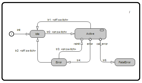
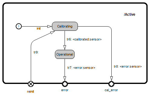
Entry and Exit Points
The Example6 state machine introduces the concepts of Entry and Exit Points, which can be used to direct one or more transitions through a single path.
1. Entry Points:
Entry points allow one or more transitions entering a state from outside to be grouped together. This can be useful if there are groups of entering transitions that need to be handled differently inside the state. It can also be used to override the history mechanism.
In the example, transition tr3 points to the reinit entry point on the Active state.
Inside Active, the transition chain continues via tr9 to the Calibrating state.
This ensures that when recovering from an error the device will be forced to Calibrating before transitioning to Operational.
2. Exit points:
Exit points allow one or more transitions exiting a state from inside to be grouped together and restricted to a certain path out of the state. They can be used to handle groups of transitions exiting to the parent state differently.
In Example 6, transition tr7 starts from the Operational state and is directed to the error exit point.
Then outside the Active state, the transition chain continues via tr4 to the Error state.
On the other hand, transition tr8 starts from the Calibrating state and it goes to the cal_error exit point.
Outside the Active state, the state machine continues with tr5, ending at the FatalError state.
This differentiation using exit points ensures that error events in the substate machine of Active are handled contextually, e.g. an error event while in Operational state is recoverable, while an error event during Calibrating is non-recoverable.
ActorClass Example6 {
	Interface {
		Port switch: PSwitch
		Port sensor: PSensor
	}
	Structure {
		external Port switch
		external Port sensor
	}
	Behavior {
		StateMachine {
			State Idle
			Transition init0: initial -> Idle

			State Active {
				subgraph {
					Transition init: initial -> Calibrating {
					}
					State Calibrating
					State Operational
					Transition tr6: Calibrating -> Operational {
						triggers {
							<calibrated: sensor>
						}
					}

					EntryPoint reinit
					Transition tr9: my reinit -> Calibrating
					ExitPoint error
					ExitPoint cal_error
					Transition tr8: Calibrating -> my cal_error {
						triggers {
							<error: sensor>
						}
					}
					Transition tr7: Operational -> my error {
						triggers {
							<error: sensor>
						}
					}
				}
			}
			Transition tr0: Idle -> Active {
				triggers {
					<on: switch>
				}
			}
			State Error

			State FatalError
			Transition tr2: Error -> Idle {
				triggers {
					<off: switch>
				}
			}

			Transition tr3: Error -> reinit of Active {
				triggers {
					<on: switch>
				}
			}
			Transition tr1: Active -> Idle {
				triggers {
					<off: switch>
				}
			}
			Transition tr4: cal_error of Active -> FatalError
			Transition tr5: error of Active -> Error
		}
	}
}
Notation
We distinguish flat finite state machines (with just one level of hierarchy) and hierarchical ones.
Flat Finite State Machine
The simpler flat finite state machines are composed of the elements shown in the following table:
| Element | Graphical Notation | Textual Notation |
|---|---|---|
| State |
|
|
| InitialPoint |
| implicit |
| TransitionPoint |
|
|
| ChoicePoint |
|
|
| Initial Transition |
|
|
| Triggered Transition |
|
|


Hierarchical Finite State Machine
The hierarchical finite state machine adds the notion of a sub state machine nested in a state. A few modeling elements listed in table below are added to the set listed above.
| Element | Graphical Notation | Textual Notation |
|---|---|---|
| State with sub state machine |
Parent State |
Sub state machine |
| Entry Point |
In sub state machine |
|
| Exit Point |
|
|
