System Structure and Parameterization (SSP)
System Structure and Parameterization (SSP) is a tool independent standard to define complete systems consisting of one or more FMUs (see Functional-Mockup-Interface [LINK: https://fmi-standard.org/]) including its parameterization that can be transferred between simulation tools. Official content is available under: https://ssp-standard.org/ .
In openPASS we use SSP to connect FMUs with each other, especially those which need communication during one simulation time step. The whole SSP is appended as vehicle component.
Inputs / SSP Structure
The following image displays the example ConnectionTest.ssp. This SSP contains one root SSD-System, the subsystem OSMPConnectionTest and two SSD-Components, that are connected with each other.
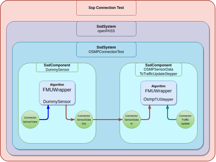
FMUs are wrapped within a SSD-Component. The example consists of two FMU’s “DummySensor” and “OSMPTrafficUpdateStepper”. To allow these two to exchange data within one timestep, they need a connection, which consists of two connectors. Either a connector gets data from outside of the SSP-System, for instance openPASS. Or two connectors which are directly connected within the SSP-System. These connections are only one directional. The example shows a common usecase of SSP: A sensor Component transfers SensorData to the TrafficUpdateStepper, which writes a DynamicSignal. This signal leaves this SSP to animate the agent.
System Structure Package SSP
On the filesystem, a SSP is a zip file, which includes one or more .ssd files together with related resources.
In our example the unpacked zip looks like this:
..\ConnectionTest.ssp
├── SystemStructure.ssd (mandatory !)
├── OSMPConnectionTest.ssd
├── ParameterValues.ssv
├── Resources
│  ├── DummySensor.fmu
│  └── OsmpTrafficUpdateStepper.fmu
In the folder structure above:
SystemStructure.ssdcan be perceived as the root of the SSP. It contains the root system.
OSMPConnectionTest.ssdA system within the root system
ParameterValues.ssvAlternative way to describe the values of SSP parameters (ref)
ResourcesThe Resources folder is for additional data, like FMUs.
Resources can be referenced FMUs. Any SSP specific files should be located in the zip root directory. SSP files are referenced from the System Structure Description file(s) through relative URIs (cf. RFC 3986). SystemStructure.ssd is the root file of the zip archive. System structure definitions (*.ssd) describe entities called Systems. Additional entries may include Parameter Values (*.ssv), Parameter Mappings (*.ssm) or Signal Dictionaries (*.ssb).
System Structure description (.ssd files)
The file “SystemStructure.ssd” is mandatory because it defines to root of the SSP. Other (*).ssd can be used to make use of more then one system, or for organisation purpose. Subsystems that are hierarchically within the root system should be listed in that SSD. Subsystems which are only present as (*).ssd but are not connected with the root. More on that in section SSD - System Structure Definition.
System Structure Parameter Values (.ssv files)
Not mandatory. Is supported in the current version of openPASS. Parameter Values describes a collection of ssd:ParameterSet A ParameterSet is a collection of parameters grouped under a name. Parameter Values can be added in two ways:
directly define it within the .ssd file in ssd:ParameterValues
create a .ssv file and reference it within the .ssd under ssd:ParameterValues
System Structure Parameter Mapping (.ssm files)
Not mandatory. Not yet implemented in current openPASS version. A parameter mapping describes a mapping between parameters. A parameter mapping can be added in two ways:
directly define it within the .ssd file in one ssd:ParameterMapping
create a .ssm file and reference it within the .ssd in one ssd:ParameterMappings
System Structure Signal Dictionaries (.ssb files)
Is not mandatory. Not yet implemented in current openPASS version. A signal dictionary is a collection of signals. There are two ways to define a signal dictionary:
directly define it within the .ssd file in ssd:ParameterMappings
create a .ssb file and reference it within the .ssd in ssd:ParameterMappings
SSD - System Structure Definition
The following example shows the definition of a system “OSMPConnectionTest”.
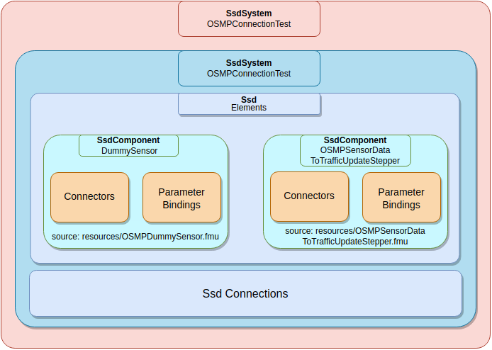
Schematic representation of OSMPConnection.ssd
In the root System, OSMPConnectionTest is defined as an Element. So this System is a subsystem of the root System. The file “OSMPConnectionTest.ssd” defines the subsystem, which consists of two Components “DummySensor” and “TrafficUpdateStepper”. Notice, how Components are listed as Elements. In general, Elements of a System can either be a System or a Component. You can think of it as a filestructure, in our example we keep it simple with just two Components in the Elements of OSMPConnectionTest.
In General
Each System consists of zero to many Elements and zero to many Connections A Element can either be a Component, a SignalDictionaryReference or a System (Subsystem). Each Element can have zero to many connectors, which are used to define Connections. Connectors can interface with the FMU model description. A Connector has a certain type (data type), and can have zero two many Annotations An Annotation is used to give additional information for any model entity, which we are using in openPASS to make OSMPConnectors (see OSI Connectors) Furthermore each Element has zero to many ParameterBindings. The parametrization of the FMUs is handled with a ParameterSet.
OSMP Connectors
By using an Annotation, we can combine three Connectors to be able to handle OSI messages. Notice, that Annotations are a valid way to extend the standard with features, which are not part of SSP yet.
                        <ssd:Annotations>
                            <ssc:Annotation type="net.pmsf.osmp">
                                <osmp:osmp-binary-variable
                                        xmlns:osmp="http://xsd.pmsf.net/OSISensorModelPackaging"
                                        mime-type="application/x-open-simulation-interface; type=SensorData; version=3.2.1"
                                        name="OSMPSensorDataOut"
                                        role="size"/>
                            </ssc:Annotation>
                        </ssd:Annotations>
Three Connectors combine with an Annotation of type “net.psmf.osmp”, by having the same name inside the osmp:osmp-binary-variable. osmp:osmp-binary-variable comes always in the same shape. Each triple of connectors must have the three following roles: base.lo, base.hi and size. base.lo and base.hi make a memory pointer, where the OSI message is allocated during simulation. size contains the memory size of the message. In combination of the three connectors the message can be passed between components Also, notice how mime-type contains crucial information. Type specifies the type of the OSI message. Version is specified as well.
FMU Parameters
The FMU inside the ssd component needs parametrization as well. These are the same parameters as the parameters of the Algorithm_FmuWrapper. To parametrize the FMU inside ssd, we define a ParameterSet inside the ParameterBindings. Important is the name attribute of the ParameterSet (name=”FMUParameters”):
                            <ssv:ParameterSet version="1.0" name="FmuParameters">
                                <ssv:Parameters>
                                    <ssv:Parameter name="Logging">
                                        <ssv:Boolean value="true"/>
                                    </ssv:Parameter>
                                    <ssv:Parameter name="CsvOutput">
                                        <ssv:Boolean value="true"/>
                                    </ssv:Parameter>
                                    <ssv:Parameter name="UnzipOncePerInstance">
                                        <ssv:Boolean value="false"/>
                                    </ssv:Parameter>
                                    <ssv:Parameter name="WriteJson_SensorView">
                                        <ssv:Boolean value="true"/>
                                    </ssv:Parameter>
									<ssv:Parameter name="WriteTrace_SensorView">
                                        <ssv:Boolean value="true"/>
                                    </ssv:Parameter>
                                    <ssv:Parameter name="Input_OSMPSensorViewIn">
                                        <ssv:String value="SensorView"/>
                                    </ssv:Parameter>
                                </ssv:Parameters>
                            </ssv:ParameterSet>
Each ssv::parameter has a sub object of the parameter type, with the attribute value containing the actual value. SSP support the following types: Real (float value), Integer, Boolean, String, Enumeration and Binary.
PriorityParameter The priority of the component is set through an annotation on component level With a higher priority, a FMU component triggers earlier then others.
                    <ssc:Annotation type="de.setlevel.ssp.scheduling">
                        <!--Standard priority is 0. Same prio is schduled parallel-->
                        <slex:co-simulation
                            priority="42"/>
                    </ssc:Annotation>
Implementation
Parsing
The first implementation detail of Algorithm SSP Wrapper, a selected SSP is loaded as vehicle component. The following picture illustrates how files are parsed and interpreted in Algorithm_SspWrapper.
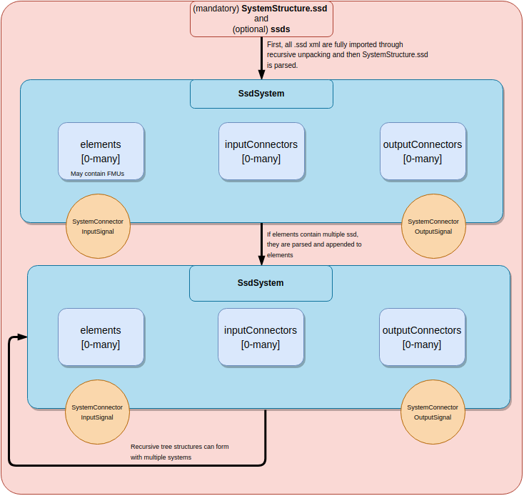
Algorithm_SspWrapper is initialized by parsing one .ssp. The zip folded contents of the .ssp is unpacked to a temporary folder and the contents are scanned for ssd files, such as the mandatory “SystemStructure.ssd”. The System described by “SystemStructure.ssd” makes the root system, any other fully parsed system is included as subsystem of that root system.
Note
One parsed ssd. System includes GroupConnectors, which contain all outer accessible connectors. A Connector is only visible from outside if it is connected with a connection. More on that in section Object Structure
Note
Should there be systems which are described by .ssd files, they must be in the elements array of the root system, or in any other system related to the root system. Is a .ssd not in any relation to the root, it is ignored!
The process of interpreting the connections is part of the system creation. Another feature of system creation is the formation of OSI Connectors we discuss in the next chapter:
OSI Connectors
The next figure describes how triples of connectors form a OSI Connector.
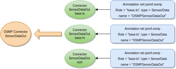
OSI connectors come in triples since OSI messages are represented with 3 integers. The integers base.lo and base.hi specify the memory location of the OSI message. base.size describes the buffer length. Through the osmp annotation, a triple of connectors are joined together. In the figures of this documentation, OSI Connectors are signaled by the purple color.
Note
The name attribute in the annotation joins the triple, whereas the connector name is relevant for the ssd system.
Note
To connect OSI connectors, they require 3 connections in the .ssd. Once the file is parsed, the 3 connections forms a complete connection in the system.
OSI connectors are responsible for writing messages. Should the OSI message of a OSI connector change, and the connector parametrized to write output, it writes the new message as soon as it changes. While json messages can be written to file directly, binary traces contain the serialized messages of much timesteps in one file. Because of that, osi messages append binary traces to message containers in their SSP system. It’s contents are written to file as soon the system destructs.
Object Structure
The implementation of SSP follows the relation of objects which the standard imposes. Mainly the SSP contains at least one System. Each System contains Elements and Connectors. Since Systems are Elements, Systems can include other Systems as subelements.
Another type of Elements are Components. One common used Component is the FMUComponent. It is good practice that FMUComponents don’t contain further subelements.
The System originating from the mandatory SystemStructure.ssd makes the root System object, containing all of it’s subsystems.
The Following picture shows ConnectionTest.ssp with two connected FMU’s.
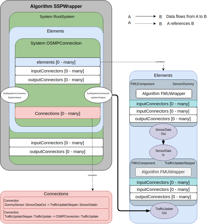
After parsing, Algorithm_SspWrapper holds only one SSP System, which is the root System defined by the systemstructure.ssd In our example, we have one subsystem: OSMPConnection, which is a Element of the root System. Within the Elements of the System OSMPConnection are two components, which are of the type FMUComponent. Each of these Components hold an instance of Algorithm_FmuWrapper. The two FMUs are connected by two OSI Connectors. To establish a connection, the following requirements need to be fulfilled:
SensorDataOut has to be a OSI connector (see section OSI Connectors)
SensorDataOut should be an output connector of SensorDummy and SensorDataIn should be an input connector of TrafficUpdateStepper. Their kind is specified as a connector attribute in the ssd file.
both connectors are connected by the connection depicted with ‘*’ in the figure.
The OSI connector SensorDataOut will propagate its SensorData to the other connector SensorDataIn. Each System can have connections, which can connect connectors of two different elements. Hence, each Connection is just a tuple of : (elementStartName, startConnectorName) -> (elementEndName, endConnectorName)
Note
While OSI Connectors are abstracted as singular units in the figure, they appear as triple in the ssd. files. Hence they require three connections in the ssd. file as well
- Example Connection between two components within the SSP (Connection ‘*’)
            <!-- DummySensor <-> TrafficStepper -->
		    <ssd:Connection startElement="DummySensor"
                            startConnector="SensorDataOut.size"
                            endElement="TrafficStepper"
                            endConnector="SensorDataIn.size"
                            suppressUnitConversion="false"/>
- Example Connection from outside the system(e.g. openPASS or another system) to a component in the system (Connection ‘**’)
            <!-- System <-> TrafficStepper -->
            <ssd:Connection startElement="TrafficStepper"
                            startConnector="TrafficUpdateOut.size"
                            endConnector="TrafficUpdateOut.size"
                            suppressUnitConversion="false"/>
Notice that the connectors SensorDataIn, SensorDataOut and TrafficUpdate belong to their Components. In the case of OSMPConnection, we are interested in the TrafficUpdate OSI message as output of the whole SSP. Therefore, it needs a connection outwards. This connection is represented by the connection ‘**’ in the figure. As you can see in the figure above, the second connection connects connector TrafficUpdateOut with the GroupConnector systemOutput. To make the connection work, the following is necessary: - TrafficUpdateOut has to be a OSI connector (see section OSI Connectors) - TrafficUpdateOut should be an output connector of TrafficUpdate and there must be three output connectors at the system OSMPConnection. These mirror the names of the three connectors forming the OSI connector on TrafficUpdateStepper. - Both connectors are connected by a connection depicted with ** in the figure.
Note
For the connectors of system level, the most minimal connectors are necessary. These only require the attribute name that mirrors the name of the connectors forming the OSI Connector.
If all conditions are met, the output connector is emplaced in the GroupConnector systemOutput. In this example there are no input connectors which are accessible form outside.
Note
Again TrafficUpdateOut makes up a pair of three connectors in the .ssd files. Notice that, if connectors inside sub elements are only accessible from outside by well defined connections.
Let’s see how these outside accessible connectors are utilized by openPASS in the next section.
SSP and openPASS
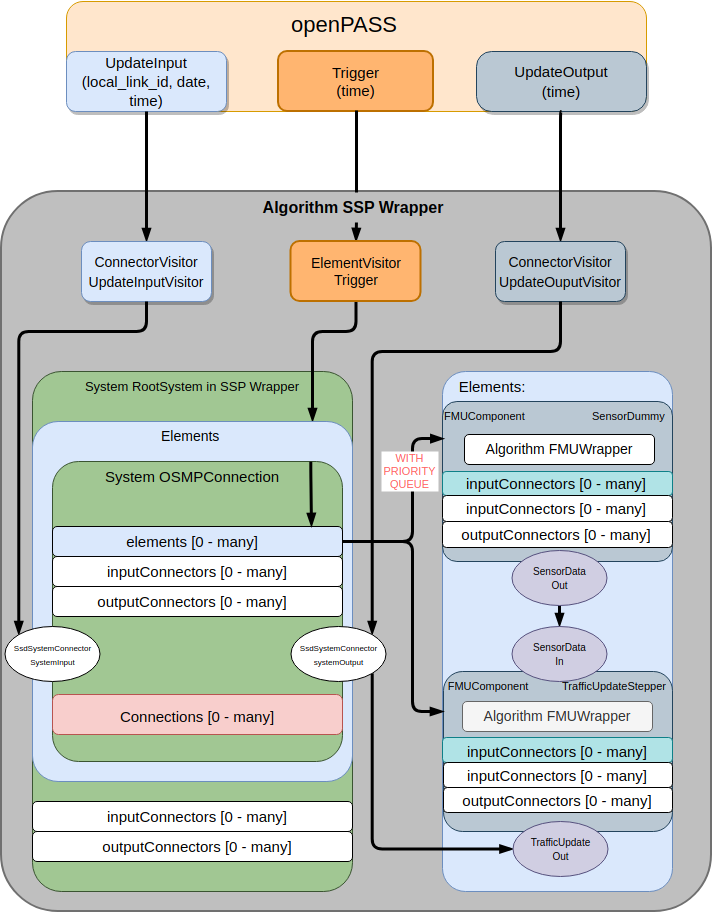
From openPASS, the Algorithm SspWrapper receives three events: UpdateInput, UpdateOutput and Trigger. For each of these events, the SSP Wrapper implementation handles them by creating Visitors following the Visitor software pattern. These Visitors visiting Elements, and allow the Elements to implement the behaviour for each visitor based on if the element is a System or a Component.
In general, we have two types of Visitors: ConnectorVisitors and ElementVisitors. In the following figure, you can see how the Visitors traverse through our OSMPConnectionExample
Components and channel communication
Trigger is an event that manifests as ElementVisitor in the Algorithm SSP Wrapper. Each Element in the root System is visited by the TriggerVisitor. A system accepts the Visitor by passing it to further subsystems and by creating a queue of FMUComponents that are stored inside the system’s elements array. Each component has a priority which is used to order the queue. Then, the queue is processed and Trigger is called on the Algorithm_FmuWrapper instances which are stored inside the FMUComponents. After each Trigger, all output Connectors are visited by the PropagateDataVisitor, which propagates OSI messages from one Connector to the next.
UpdateInput and UpdateOutput are ConnectorVisitors. For each System in the root system, they visit the SystemConnectors systemInput and systemOutput. GroupConnectors can be connected to other connectors (see SSP Connections). Their job is to delegate ConnectorVisitors to their connected counterparts. The UpdateInputVisitor and UpdateOutputVisitor follow the GroupConnectors systemInput/systemOutput down to it’s OSI Connectors. Once these Visitors visit a OSIConnector, they can perform UpdateInput and UpdateOutput, if the OSI Connector is a connector of a FMUComponent.
Note
UpdateInput and UpdateOutput handling is still experimental. Since we need to decide to continue in calling UpdateInput/UpdateOutput on the FMU, or to refactor OSMPFmuHandler.
At the beginning of the simulation, the Init Visitor is a unique ElementVisitor, which will traverse through the System and trigger on every FMU the init procedure.
Limits
The current implementation of SSP in the SSP Wrapper is not a full implementation of the SSP Standard but rather a solution to connect more then one FMUs together. Currently, these SSP features are not part of Algorithm SspWrapper :
The standard allows usage of ids that can be used to refer any BaseElement in SSP
Other annotations besides OSMP Connectors and the component priority are ignored
Top Level meta data is not parsed
units and transformation between units are not supported
XML Element Choice : “Transformation Choice” as GType choice (for Connections) is not supported
SSP as component of Systems is not implemented
ParameterMapping (SSM) for automatic unit-mapping and name transformations in parameter binding is not implemented
Signal directories (SSB) as element of systems for cross hierarchical signal pools (e.g for buses) (and Signal Directory Reference) are not implemented
Default Experiment (with startTime and StopTime) is not used and ignored, the experiment control comes through openPASS events
Connectors of type string and binary data are not supported
Outputs
For debugging purposes we allow to write out intermediate results during Simulation.
FolderStructure
The following folder structure shows the output files of our example.
..\results
├── ssp
│  ├── Agent0xxx
│  │   ├──OsmpConnectionTest
│  │   │   ├── DummySensor
│  │   │   │  ├── JsonFiles
│  │   │   │  └── BinaryTraceFiles
│  │   │   ├── TrafficUpdateStepper
│  │   │   │   ├── JsonFiles
│  │   │   │   └── BinaryTraceFiles
│  │   │   └──
│  │   └──
│  └──
└──
- In the folder structure above:
sspis always the root of the output structureAgent0xxx: the output is grouped by the agent who produced it (Agent0 -> Agent0000, Agent1 -> Agent0001)the output is grouped by its producing System name
Further, the output is grouped by Components
There are two different possible output files: Json and BinaryTrace
Json files for - For every timestep a json file containing the connector’s OSI message will be created
BinaryTrace files for - Serialized OSI message as string from a specified connector
WriteMessageParameters
We can specify for each component if json and/or binary traces are written to a file by using the parameter set “WriteMessageParameters”. The following shows an example:
                            <ssv:ParameterSet version="1.0" name="WriteMessageParameters">
                                <ssv:Parameters>
                                    <!-- <ssv:Parameter name="WriteJson_SensorData">
                                        <ssv:String value="OSMPSensorDataOut"/>
                                    </ssv:Parameter>
									<ssv:Parameter name="WriteTrace_SensorData">
                                        <ssv:String value="OSMPSensorDataOut"/>
                                    </ssv:Parameter> -->
                                </ssv:Parameters>
                            </ssv:ParameterSet>
How to read these parameters: - WriteJson_SensorData: We write json outputs for the connector triple “OSMPSensorDataOut” - WriteTrace_SensorData: We write binary traces for the connector triple “OSMPSensorDataOut”