Algorithm_Longitudinal
This module is responsible for the control of the vehicle’s longitudinal behavior. It receives the command variables from a driver behavior model and generates the accelerator and brake pedal position and the current gear of the driver to match these command variables. The pedal positions and the gear can then be forwarded to a vehicle dynamics module like Dynamics_RegularDriving. The actuation of the clutch pedal is currently not simulated by the modul
Detailed description of the module’s features
Inverted longitudinal dynamics model
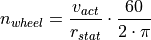
The inverted longitudinal dynamics model produces  by utilizing an inverted powertrain and brake system model. The powertrain model
and all of its parameters and state variables are illustrated in the following image.
The brake model is not worth illustrating, as it directly applies on the required acceleration
by utilizing an inverted powertrain and brake system model. The powertrain model
and all of its parameters and state variables are illustrated in the following image.
The brake model is not worth illustrating, as it directly applies on the required acceleration
 of the vehicle.

Illustration of the powertrain model and its parameters and state variables
The core element of all calculations in this model is speed and acceleration.
The speed  at the wheels is constraint by the current velocity
 of the vehicle and the static wheel radius
  :
:
where is specified in  (revolutions per minute) and is
defined in
(revolutions per minute) and is
defined in  , which requires the conversion term at the end of the equation.
As the equation also illustrates, only a simple rolling relation defines the
model and there is no simulation of tire-road-friction and tire slip involved.
, which requires the conversion term at the end of the equation.
As the equation also illustrates, only a simple rolling relation defines the
model and there is no simulation of tire-road-friction and tire slip involved.
The speed  of the engine is constraint by the speed
of the wheels, the ratio
of the engine is constraint by the speed
of the wheels, the ratio  of the axle, and the
current ratio
of the axle, and the
current ratio  of the gearbox, depending of the current gear:
The required acceleration determines the torque  at the wheels, as the overall mass
  of the vehicle has to be accelerated by
this torque:
of the vehicle has to be accelerated by
this torque:

As the equation illustrates, no driving resistances other than the inertia of
the vehicle are simulated by this model. The required torque
at the wheels must be generated by the engine, considering the ratios of the
powertrain:
As the current speed of the engine, the required acceleration
of the vehicle, and the required torque  of the
engine are known or defined by the above equations, this knowledge can be used
to determine the estimated positions of the accelerator and the brake pedal or
to calculate the optimal gear for the required acceleration ,
if a positive acceleration is needed. For the accelerator pedal and optimal gear
calculation, there is still some missing knowledge about the engine itself.
The relationship between the current engine speed and the
possible engine torque is determined by a simple engine map,
which is illustrated in the following image:
of the
engine are known or defined by the above equations, this knowledge can be used
to determine the estimated positions of the accelerator and the brake pedal or
to calculate the optimal gear for the required acceleration ,
if a positive acceleration is needed. For the accelerator pedal and optimal gear
calculation, there is still some missing knowledge about the engine itself.
The relationship between the current engine speed and the
possible engine torque is determined by a simple engine map,
which is illustrated in the following image:

Simplified engine map used for the inverted powertrain model
The engine map is defined by two characteristic curves:
 defines the maximum torque, which can be produced by the
engine at a specific engine speed . This is directly connected
with the maximum possible actuation of the accelerator pedal.
defines the maximum torque, which can be produced by the
engine at a specific engine speed . This is directly connected
with the maximum possible actuation of the accelerator pedal. defines the drag torque, which is produced by the engine
at a specific engine speed , if the accelerator pedal is not
actuated at all.
defines the drag torque, which is produced by the engine
at a specific engine speed , if the accelerator pedal is not
actuated at all.
The two characteristic curves are only defined between the minimum and maximum
possible speed of the engine. As the two characteristic curves are directly
related to a full actuation ( ) and no actuation
(
) and no actuation
( ) of the accelerator pedal, the estimated pedal
position for the accelerator pedal , which produces the
currently required engine torque , can be calculated by linear
interpolation between these two characteristic curves at the current engine
speed .
) of the accelerator pedal, the estimated pedal
position for the accelerator pedal , which produces the
currently required engine torque , can be calculated by linear
interpolation between these two characteristic curves at the current engine
speed .
Analogous for the brake pedal position:
The maximum actuation of the brake pedal (
 ) is
directly connected with the maximum possible deceleration of the vehicle, which
is simply set to 1G (
) is
directly connected with the maximum possible deceleration of the vehicle, which
is simply set to 1G ( ).
).No actuation of the brake pedal (
) also produces no
deceleration.
Between these two possible decelerations, the estimated brake pedal position to
produce the required acceleration is calculated by linear
interpolation.
The logic for the calculation of the static controller output ,
utilizing the considerations above, is defined as follows:
If the required acceleration is smaller than zero, it can be
produced by the engine drag torque or the brake system. If the engine drag
torque at the current engine speed is not
strong enough to meet the engine torque , which would be
necessary to produce , an additional actuation of the brake
pedal is applied (the driver does not open the clutch, so the engine drag torque
is also applied to the wheels). This mechanism is not considering a change in
gears, but uses the current gear of the gearbox (the driver does not consider to
shift down for a stronger effect of the engine drag torque).
If the required acceleration is greater than or equal to zero,
it can only be produced by the powertrain. First of all, the optimal gear to
produce the engine torque required for is
calculated, which is described in the subsequent subsection.
With this chosen gear, the current engine speed is calculated.
is used to determine the maximum engine torque
and the engine drag torque from the characteristic curves.
As these two values are connected to a full actuation and no actuation of the
accelerator pedal, the estimated accelerator pedal position, which is necessary
to produce the required acceleration , can be calculated by
linear interpolation.
The state variable is received from the module Sensor_Driver,
the required acceleration is received from a driver behavior
model, and the vehicle parameters , , , per gear,
and the information about the engine map are received from the module Parameters_Vehicle.
The calculations above are done in the function CalculatePedalPositions, which is called in the function CalculatePedalPositionAndGear of Algorithm_Longitudinal.
Algorithm for optimal gear determination
The algorithm for the determination of the optimal gear for the required
acceleration is implemented in the function CalculateGearAndEngineSpeed.
It is called within the function CalculatePedalPositionAndGear of Algorithm_Longitudinal,
which applies the inverted longitudinal dynamics model.
The algorithm receives the current velocity of the vehicle and the required acceleration .
Within a for-loop over all gears, the engine speed is calculated
for each gear, which would result from the current velocity ,
as well as the maximum engine torque and the engine drag
torque resulting from these engine speeds. Violating the
minimum engine speed  and the maximum engine speed
  is not considered in this step (resulting engine speeds are written as they result
from the powertrain calculation and the engine torques are set to the lower or
upper limits of the characteristic curves respectively, if the engine speed
range is violated).
is not considered in this step (resulting engine speeds are written as they result
from the powertrain calculation and the engine torques are set to the lower or
upper limits of the characteristic curves respectively, if the engine speed
range is violated).
The results above are further processed in a second for-loop over all gears. The following aspects are checked to determine, if a gear fits the current required state:
Is the resulting engine speed
within the range of
and ?Is the resulting engine torque
to produce the required
acceleration within the range of and ?
The lowest gear that fits these criteria sets a Boolean foundGear true and the
results (gear number and resulting engine speed ) are written in
the result vector. This is done for all further gears, until a gear does not fit
the requirements anymore. This initiates the return of the last sufficient gear
and its resulting engine speed . A short example should
illustrate this logic:
The 2nd gear activates the Boolean foundGear, because
does
not exceed anymoreThe 4th gear activates the return of the results, because the required engine torque
would exceed the maximum possible engine torque
at the corresponding engine speed The algorithm chooses the 3rd gear as optimum and returns it and its corresponding engine speed
This logic therefore guarantees, that always the highest possible gear is chosen by the driver.