CAN Implementations#
The framework contains already 3 different CAN components:can_com_sim.sdv - CAN implementation based on asc text filecan_com_sockets - CAN implementation based on socketscan_com_silkit.sdv - CAN implementation based on Vector SIL-Kit
CAN implementation based on asc text file#
The can messages are communicated by reading and writing the messages which are in ASC file format.
ASC file in CAN simulation:
It is a plain text file format used to store data in the American Standard Code for Information Interchange (ASCII) standard.
IT is important for logging and analyzing CAN bus traffic. They are human-readable text files that log each CAN frame with a timestamp and message details.
These ASC files support basic characters like letters, numbers and punctuation.
Each character matches with the character in the ASCII code.
The CAN messages which are encoded in ASCII format are read and written via the given .asc file.
Structure of a CAN .asc File:
A typical .asc file from a CAN logger (like Vector CANalyzer or CANoe) might look like:
<timestamp> <channel> <message type> <ID> <DLC> <data bytes> [flags]
Example .asc file:
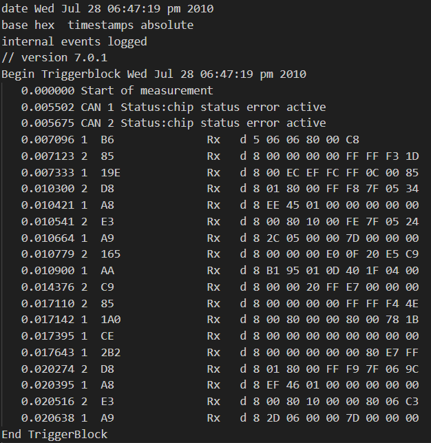
Each line includes:
Elements |
Definition |
|---|---|
0.007096 |
Timestamp in seconds, When the message was received |
1 |
CAN channel number |
B6 |
Message ID(in decimal or hexadecimal) |
Rx |
Message direction (Rx = received, Tx = transmitted) |
d |
Frame type (d = data frame, r = remote frame) |
5 |
DLC (Data Length Code), Number of data bytes |
06 06 80 00 C8 |
Actual payload of the CAN message |
Usage in CAN Communication:
Logging: Capturing CAN traffic during testing or operation.
Debugging: Analyzing communication issues between ECUs (Electronic Control Units).
Simulation: Replaying CAN traffic to simulate real-world scenarios.
Data Analysis: Feeding into tools/scripts for performance or fault analysis.
Interoperability: Sharing logs between different tools and teams.
How to load and configure VAPI can simulation component#
When we need to use the can simulation component from VAPI, the already defined can messages in .asc file can be given in a .toml file.
[Configuration]
Version = 100

[[Component]]
Path = "task_timer.sdv"
Class = "TaskTimerService"

[[Component]]
Path = "data_dispatch_service.sdv"
Class = "DataDispatchService"

[[Component]]
Path = "can_com_sim.sdv"
Class = "CAN_Com_Sim"
[Component.Parameters]
Source="asc_reader_test.asc"
Target="asc_writer_test.asc"
an example toml file through which we should include the reader and writer .asc files.
Path = "task_timer.sdv"
Class = "TaskTimerService"
include the vapi timer library and relevant declared class name for using timer related services.
Path = "data_dispatch_service.sdv"
Class = "DataDispatchService"
include the vapi data dispatch service for dispatching can data between vapi and application.
Path = "can_com_sim.sdv"
we need to include the required library of vapi can simulator
Class = "CAN_Com_Sim"
we should mention the declared class name of relevant library which we are going to use.
Source="asc_reader_test.asc"
Target="asc_writer_test.asc"
mention the reader and writer .asc files through which we will be reading and writing can messages.
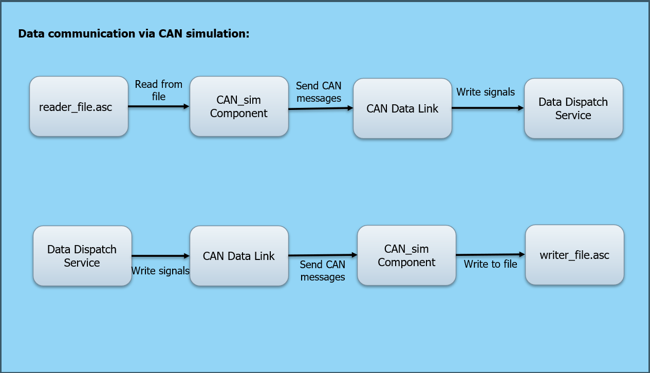
The diagram shows that the vapi can simulation component reads the can messages from .asc file, send messages via data link to data dispatch service.
In order to write messages in to .asc file, the can messages are send via vapi can simulation component from data link to writer .asc file.
CAN implementation based on socket can#
It is a software based CAN bus, through which developers can develop and test the CAN nodes without the actual CAN hardware.
It is a set of open-source CAN drivers and a networking stack that is part of the Linux kernel.
It allows CAN devices to be treated like network interfaces, making it easier to develop and debug CAN-based applications.
Allow developers to use familiar socket programming techniques for CAN communication.
Support both Classical CAN and CAN FD (Flexible Data-rate).
How to configure VAPI socket can component#
When we need to use the socket can from VAPI, we can define them in a .toml file.
[Configuration]
Version = 100

[[Component]]
Path = "can_com_sockets.sdv"
Class = "CAN_Com_Sockets"
canSockets=["vcan3"]
an example toml file
Path = "can_com_sockets.sdv"
we need to include the required library
Class = "CAN_Com_Sockets"
we should mention the declared class name of relevant library which we are going to use.
canSockets=[<"name_of_can_hardware">]
give the name of the socket can which we will be using.
CAN data communication via socket can:
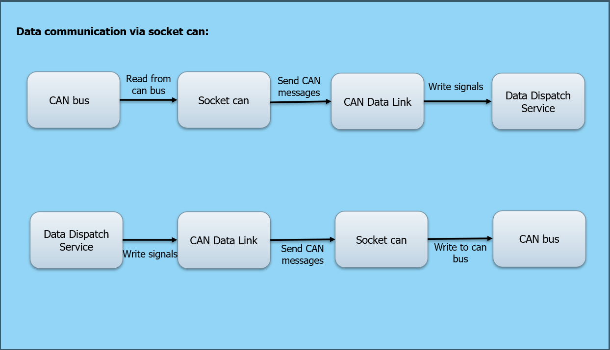
The above image shows that the socket can reads the can messages from can bus, send messages to application via data link and vapi services.
In order to write messages in to can bus, the can messages are send via socket can from data link to can bus.
Tools for SocketCAN#
The can-utils package provides user-space tools for working with SocketCAN. Some commonly used tools include:
candump: Displays and logs CAN traffic.
cansend: Sends a single CAN frame.
cangen: Generates random CAN traffic.
cansniffer: Monitors and highlights changes in CAN data.
Real CAN Interface (e.g., USB-CAN adapters):
If you have a physical CAN device (like a USB-CAN adapter), you can use SocketCAN
Linux has built-in support for CAN via SocketCAN, which treats CAN interfaces like network interfaces.
Steps: - Connect your CAN device (e.g., Peak, Kvaser, or MCP2515). - Load the appropriate kernel module (e.g., can, can_raw, vcan, usbcan, etc.). - Bring up the CAN interface:
sudo ip link set can0 up type can bitrate 500000
Use tools like:
candump (to read CAN frames)
cansend (to send CAN frames)
can-utils package (install via sudo apt install can-utils)
Simulated CAN Interface (Virtual CAN):
If you don’t have hardware, you can simulate CAN communication using virtual CAN (vcan). Steps to simulate: 1. Load vcan module
sudo modprobe vcan
Create a virtual CAN interface
sudo ip link add dev vcan0 type vcan
Bring it up
sudo ip link set up vcan0
Send and receive messages
cansend vcan0 123#DEADBEEF
candump vcan0
This is great for testing CAN applications without needing physical devices.
Working with CAN hardware on linux:
Note
Since in windows, working with socket can is not possible, we have explained about working in linux. we can use vcan interface of SocketCAN when we don’t have the actual CAN hardware.
To work with actual Controller Area Network (CAN) hardware, we need:
A CAN interface device (e.g., USB-to-CAN adapters like Peak, Kvaser, or SocketCAN-compatible devices).
A physical CAN bus setup (e.g., ECUs, sensors, or other CAN nodes).
Proper termination (120-ohm resistors at both ends of the bus).
when we need to do the software setup, follow below steps for linux:
sudo modprobe can
sudo modprobe can_raw
sudo modprobe mttcan  # or your specific driver
sudo ip link set can0 up type can bitrate 50000
Installation of SocketCAN on linux system:
Step 1: Load the vcan Kernel Module:
sudo apt update
sudo apt install can-utils
sudo modprobe vcan
It install the can-utils package, which provides tools like candump, cansend, etc.
Step 2: Create a Virtual CAN Interface:
sudo ip link add dev vcan0 type vcan
Step 3: Bring the Interface Up:
sudo ip link set up vcan0
Step 4: verify the interface:
ip link show vcan0
Use above mentioned commands when we use a virtual CAN interface for testing
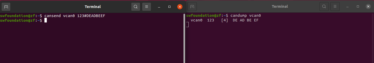
Communication Test:
After successful installation of can-utils and brought up the can interface, we can test how the vcan works by opening two different terminals.
Give the below mentioned commands to send and receive a can message.
Send a CAN Frame:
cansend vcan0 123#DEADBEEF
Receive CAN Frames:
candump vcan0
Explanation of test code using socket can:
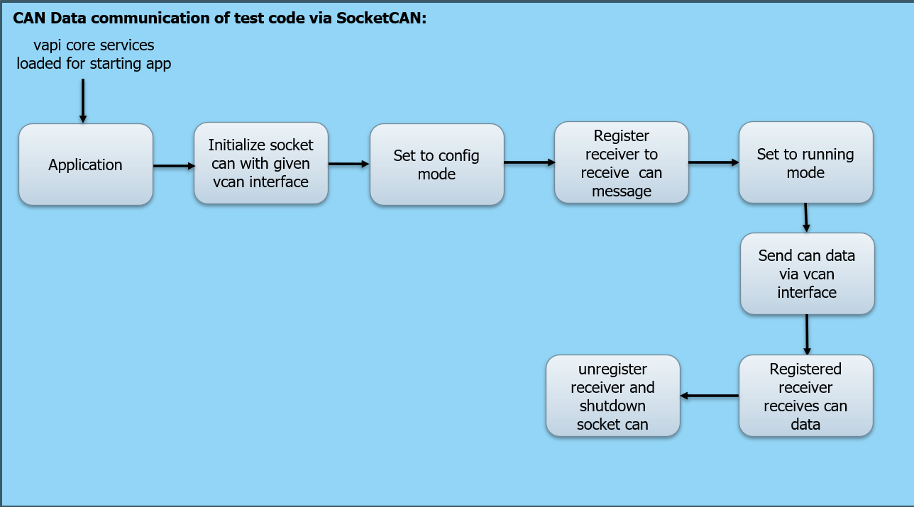
The above image shows that the application which has to send or receive can data will be started by loading vapi core services.
The vcan interfaces through which we are going to send and receive can messages should be initialized.
After setting it to configuration mode, the receivers who are going to receive messages should be registered.
The data will be send via the configured vcan interface in the running mode.
Once the data was send, the registered receiver receives data immediately.
After sending and receiving all data, the receiver should be unregistered and socket can will be closed, through which we cannot start the communication.
CAN implementation based on Vector SIL-Kit#
Vector Sil-Kit
Vector SIL Kit, is an open-source software library developed by Vector Informatik for connecting Software-in-the-Loop environments.
It’s designed to facilitate communication between various simulation tools, virtual ECUs, emulators, and test systems—especially useful in automotive and embedded systems development.
It supports various vehicle network controllers like CAN, Ethernet, FlexRay and LIN.
provides publish/subscribe mechanism for data communication.
Start with Vector Sil-Kit
How to install:
clone the <https://github.com/vectorgrp/sil-kit>_
Initialize submodules:
git submodule update --init --recursive
Build using CMake:
mkdir build
cd build
cmake ..
make
Vector Sil-Kit Utilities
sil-kit-registry:
It is the mandatory part of the vector Sil-Kit which provides connection between simulation participants.
provides SIL Kit participants with information of available participants and how to connect to them
The SIL Kit Registry must be started before other SIL Kit participants.
Usage: Open a separate terminal
./sil-kit-registry
sil-kit-system-controller:
It defines the required participants for the simulation.
Usage: Open a separate terminal
./sil-kit-system-controller ./Participant1 ./Participant2
sil-kit-monitor:
It visualizes the states of the participants
Usage: Open a separate terminal
./sil-kit-monitor
Participants can be configured to coordinate their simulation start and stop behavior with other participants through use of the Lifecycle Service.
To synchronize their virtual time with others, a participant can use the Time Synchronization Service.
How to configure VAPI Sil-Kit Can component:#
When we need to use the VAPI Sil-Kit CAN, we can define them in a .toml file.
[Configuration]
Version = 100

[[Component]]
Path = "task_timer.sdv"
Class = "TaskTimerService"

[[Component]]
Path = "data_dispatch_service.sdv"
Class = "DataDispatchService"

[[Component]]
Path = "can_com_silkit.sdv"
Class = "CAN_Com_SilKit"
[Component.Parameters]
DebugInfo = true
SyncMode = true
SilKitParticipantName = "CAN1"
CanSilKitNetwork = "PrivateCAN"
RegistryURI = "silkit://localhost:8500"
SilKitConfig = """{
         "Logging": {
               "Sinks": [ { "Type": "Stdout", "Level": "Info" } ]
              },
              }"""

[[Component]]
Path = "can_datalink.sdv"
Class = "CAN_data_link"
an example toml file through which we can include the dependent libraries and the required configuration for Sil-Kit.
Path = "task_timer.sdv"
Class = "TaskTimerService"
include the vapi timer component and relevant declared class name for using timer related services.
Path = "data_dispatch_service.sdv"
Class = "DataDispatchService"
include the vapi data dispatch component for dispatching can data between vapi and application.
Path = "can_com_silkit.sdv"
we need to include the required library of vapi Sil-Kit CAN.
Class = "CAN_Com_SilKit"
we should mention the declared class name of relevant library which we are going to use.
DebugInfo = true
It will enable or disable debug information
SyncMode = true
This is to inform that we will be using which configuration mode, either synchronous or asynchronous.
SilKitParticipantName = "CAN1"
Unique identifier for the participant in the Sil-Kit simulation
CanSilKitNetwork = "PrivateCAN"
name of the CAN network in Sil-Kit
RegistryURI = "silkit://localhost:8500"
URI for connecting to the Sil-Kit registry
SilKitConfig = """{
         "Logging": {
               "Sinks": [ { "Type": "Stdout", "Level": "Info" } ]
              },
              }"""
required Sil-Kit configuration
Path = "can_datalink.sdv"
Class = "CAN_data_link"
include the vapi datalink component for data communication between Sil-Kit and data dispatch component.
How to run the SilKit CAN Communication Tests#
This guide provides instructions on how to execute the manual tests for the SilKit CAN communication system, including the can_reader and can_writer components.
Prerequisites:
Before running the tests, ensure the following:
Operating System: Ubuntu (or a Linux distribution with gnome-terminal installed) or Windows.
Dependencies: - sil-kit-registry and sil-kit-system-controller binaries are available in the directory: <output_build_folder>/_deps/silkit-src/SilKit/bin/ - gnome-terminal is installed on your system (Linux only).
Build: The project has been built successfully, and the binaries for can_reader and can_writer are available in the directory: <output_build_folder>/<compiler_version>/tests/bin/
Test Components
The tests involve the following components:
sil-kit-registry: Manages the SilKit network.
sil-kit-system-controller: Controls the lifecycle of SilKit participants.
can_writer: Sends CAN messages to the network.
can_reader: Receives CAN messages from the network.
Instructions for Linux
Step 1: Start the SilKit Utilities:
Open a new terminal, navigate to the directory containing the sil-kit-registry and executes it
sil-kit-registry.exe
Open another terminal, navigate to the directory containing the sil-kit-system-controller and run the below command
sil-kit-system-controller.exe can_writer.exe can_reader.exe
Step 2: Run the CAN Writer
In a new terminal, navigate to the directory containing the can_writer executable:
can_writer.exe
The can_writer will send different CAN messages to the network. Each message will be logged in the terminal.
Step 3: Run the CAN Reader
In another terminal, navigate to the directory containing the can_reader executable:
can_reader.exe
The can_reader will receive and log the CAN messages sent by the can_writer. Each message will be logged in the terminal.
Instructions for Windows:
Step 1: Start the SilKit Utilities
Before running the executables, copy the SilKit.dll and SilKitd.dll DLLs from the SilKit source directory <..>_depssilkit-srcSilKitbin to the <..>testbin directory.
Open two Command Prompt or PowerShell windows
In the first window, navigate to the SilKit bin directory and run:
sil-kit-registry.exe
In the second window, run:
sil-kit-system-controller.exe can_reader can_writer
Step 2: Run the CAN Writer
Open a new Command Prompt or PowerShell window and navigate to the directory containing the can_writer binary:
can_writer.exe
The can_writer will send different CAN messages to the network. Each message will be logged in the terminal.
Step 3: Run the CAN Reader
Open another Command Prompt or PowerShell window and navigate to the directory containing the can_reader binary:
can_reader.exe
The can_reader will receive and log the CAN messages sent by the can_writer. Each message will be logged in the terminal.
Expected Output:
CAN Writer: Logs the messages being sent, including the CAN ID, data length, and data content in the terminal.
CAN Reader: Logs the messages being received, including the CAN ID, data length, and data content in the terminal.
Troubleshooting:
Binaries Not Found: Ensure the sil-kit-registry, sil-kit-system-controller, can_writer, and can_reader binaries are built and located in the correct directories.
Network Issues: Ensure the RegistryURI in the configuration matches the address of the sil-kit-registry.
Additional Notes:
The can_writer and can_reader configurations are hardcoded in their respective source files. If you need to modify the configurations (e.g., participant names, network names, or registry URI), update the source code and rebuild the binaries.
The tests are designed to run in synchronous mode (SyncMode = true). Ensure this setting is consistent across all components.
Explanation of test code using VAPI Sil-Kit CAN:
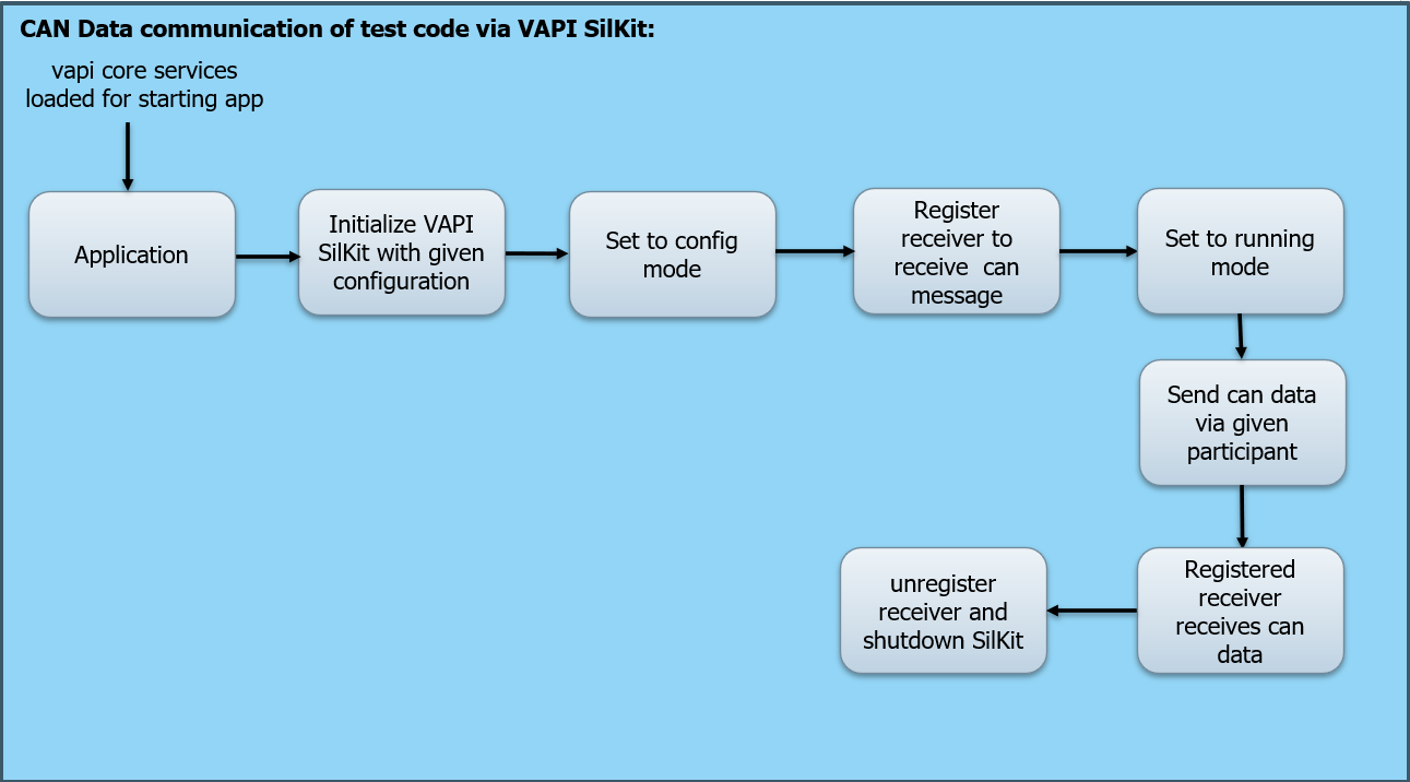
The above image shows that the application which has to send or receive can data will be started by loading vapi core services.
The VAPI Sil-Kit should be initialized with the required configuration.
After setting it to configuration mode, the receivers who are going to receive messages should be registered.
The data will be send via the configured participant in the running mode.
Once the data was send, the registered receiver receives data immediately.
After sending and receiving all data, the receiver should be unregistered and VAPI Sil-Kit will be shutdown.