Visual Perception
As previously mentioned, visual perception plays a superior role in information acquisition for drivers, since the majority of information is perceived through this channel. SCM imitates the gaze behaviour of a human driver and allocates the driver’s field of view. This determines the perception of optical information by SCM.
To explain the visual perception processes implemented in SCM, the following section firstly defines the concept of Areas of Interest (AOIs). Afterwards, general gaze allocation mechanisms are described. Gaze directions are then linked to their mapping of fields of view. Specific gaze allocation processes concerning information request mechanisms, such as bottom-up and top-down requests, are described afterwards. Lastly, visual perception in SCM can also be controlled explicitly, which is described in the final section of this chapter.
Areas of Interest (AOIs)
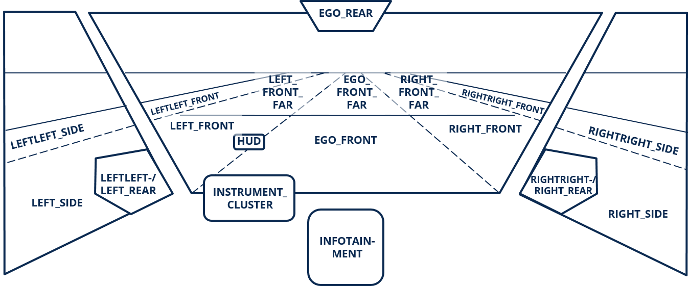
SCM perceives optical information from surrounding traffic objects by fixating a specific Area of Interest. The AOIs available to SCM and their naming are illustrated in Fig. 7.

Fig. 7 AreasOfInterest available to SCM
(It is important to notice that the distinction between FRONT and FRONT_FAR is not done based on specific relative distances, but on the sequence of the surrounding traffic objects. Therefore, an object associated with AOI EGO_FRONT can be farther away than an object associated with AOI LEFT_FRONT_FAR, for instance.)
When and for how long the driver looks at a certain AOI, is governed by the so-called GazeControl. The main task of GazeControl is to fixate one of these AreasOfInterest for a specific fixation time and then allocate the gaze to another AOI. The gaze allocation between two fixation targets is called a saccade and the duration of a saccade mainly depends on the necessary amplitude of the gaze allocation. Due to physiological reasons, humans are not able to visually perceive information during a saccade, but the saccade durations are of such short manner that the visual cortex interpolates the perceived information and the brain does not sense the lack of information. The three aspects fixation duration, next target of fixation, and saccade duration are all part of the stochastic process of GazeControl. Depending on the fixation probabilities for the AreasOfInterest, two subsequent gazes can also be allocated on the same AOI. See General mechanism of the gaze movement algorithm for more information about the general mechanism of the gaze movement algorithm.
The reason for the simulation of gaze behaviour is deeply linked to the visual perception models of SCM. Humans are not able to visually perceive their whole environment at once. The field of view expands around the gaze fixation axis about 180 to 210 degrees horizontally and 130 degrees vertically. Within this field of view, the visual sensory system is only able to perceive and cognitively process optical information in a very small area, which is called the fovea centralis. The fovea centralis expands only about 1 to 2 degrees around the gaze fixation axis. The more the eccentricity of optical stimuli increases to the gaze fixation axis, the more all visual perception functions processing this stimuli vastly decrease in performance. Several sources in literature define a useful field of viewas follows: the area in which optical information can still be cognitively processed, but the quality of the perceived information is largely reduced. The reported size of this useful field of view varies between 30 to 60 degrees, depending on the cited source. The rest of the field of view is simply called periphery. Optical stimuli in this part of the field of view cannot be cognitively processed, but they can cause the initiation of a gaze allocation. This mechanism is called bottom-up control of visual attention. Fig. 8 illustrates the different parts of the field of view and how they are reffered to in SCM.

Fig. 8 Illustration of the different parts of the human’s field of view
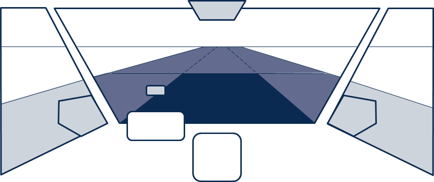
The link between the two aspects of gaze direction and different parts of the field of vision consists of a matching algorithm that determines which AreasOfInterest are assigned to which part of the field of view, so the visual perception models can be applied accordingly. Fig. 9 illustrates an exemplarily assignment for a fixation of the AOI EGO_FRONT.

Fig. 9 Exemplarily assignment of AreasOfInterests to the different parts of the field of view when fixating EGO_FRONT (Colour code according to Fig. 8)
A full description of the mechanism for AOI assignments can be found here.
Gaze Control
General mechanism of the gaze movement algorithm
The gaze movement algorithm is executed by the function AdvanceGazeState. The fixation probability for each AOI is described by a value between 0.0 and 1.0. The time, how long the driver will fixate an AOI, is described by a fixation duration (expressed in milliseconds). All intensities and fixation durations are drawn from distribution functions. The parameters of these distribution functions were derived from gaze behaviour measurements in human subject studies within real world driving situations on motorways. The context sensitive parameterization is controlled by bottom-up and top-down mechanisms for the visual attention.
To select a new gaze target, all intensities are listed and then sampled. The connection between two gaze fixations is accomplished by a saccade, whose duration is calculated using a stochastic model for the saccade duration. It also considers if a saccade has to cross a small or a large amplitude in gaze angle. For saccades between the FRONT, SIDE, REAR, and interior AOIs a long saccade is necessary. Short saccades are sufficient if the change of gaze target takes place among the FRONT AreasOfInterest or if the gaze target does not change at all. Durations for short and long saccades are drawn from different distribution functions. After the saccade is completed, the new gaze target will be fixated for a specific sampled fixation duration for the associated AOI.
An additional physiological mechanism addressed by the model is called saccadic suppression. Saccadic suppression describes the phenomenon, that the human eye is not able to perceive optical information during a saccade. This suppression of information acquisition already starts a few milliseconds before the eye even begins moving. It further lasts a few milliseconds after the saccade has already been completed. This addresses a minor part of the driver’s reaction time model, which is associated with gaze allocation.
Mapping of field of view parts to current gaze direction
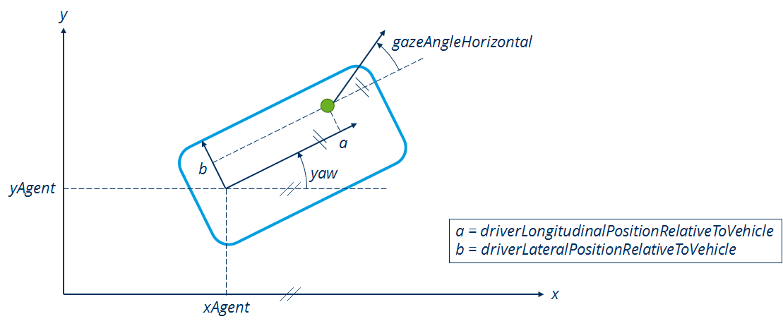
The field of view of the driver as described in the overview section is currently modelled as a two-dimensional cone section in the horizontal layer. Therefore, no vertical gaze angle exists and the assignment of the field of view parts is not depending on any such vertical allocations (of course, there can always only be one fovea). For modelling the drivers gaze direction and the field of view allocated to that, at first the position of the driver is necessary. Fig. 10 illustrates all the relevant values and the definition of the driver’s gaze direction.

Fig. 10 Definition of the driver’s horizontal gaze angle according to the inertial coordinate system (xAgent - position of the vehicle in the x direction; yAgent - position of the vehicle in the y direction; a/b - longitudinal/lateral position of the driver within the vehicle; gazeAngleHorizontal - horizontal angle of the drivers gaze direction)
The driver’s relative position to their own vehicle indicates the eye point. The values depend on the vehicle model itself which is why they are taken from the vehicle parameter data. As shown in Fig. 10, the horizontal gaze angle is defined in relation to the vehicles longitudinal axis, so a gaze angle of 0° is equal to a gaze straight ahead. The range of values is also similar to that of the yaw angle:
Gaze to the right: -180 degree < gazeAngleHorizontal < 0
Gaze to the left: 0 < gazeAngleHorizontal < 180 degree
The gaze angle itself depends on the object the driver is currently fixating which is considered the current AOI for the fovea. There are two ways how the orientation of an object can be communicated to the driver model. Orientation is hereby considered as the angle of an object relative to the driver. It is equally defined as the gaze angle in terms of range of values and definition of 0°. The two options are:
The field of view expands around the gaze fixation axis about 180° to 210° horizontally and 130° vertically. Within this field of view, the visual sensory system is only able to perceive and cognitively process optical information in a very small area, which is called the fovea centralis. The fovea centralis expands only about 1° to 2° around the gaze fixation axis. The more the eccentricity of optical stimuli increases to the gaze fixation axis, the more all visual perception functions processing this stimuli vastly decrease in performance. Several sources in literature define a useful field of view as follows: the area in which optical information can still be cognitively processed, but the quality of the perceived information is largely reduced. The reported size of this useful field of view varies between 30° to 60°, depending on the cited source. The rest of the field of view is simply called periphery. Optical stimuli in this part of the field of view cannot be cognitively processed, but they can cause the initiation of a gaze allocation. This mechanism is called bottom-up control of visual attention.
Fig. 8 illustrates the different parts of the field of view and how they are reffered to in SCM.t mirror): RightMirrorOrientationRelativeToDriver * HUD (if applicable): HeadUpDisplayOrientationRelativeToDriver * INSTRUMENT_CLUSTER: InstrumentClusterOrientationRelativeToDriver * INFOTAINMENT (if applicable): InfotainmentOrientationRelativeToDriver
For all other AOIs, the orientation is dynamically processed in SensorDriver according to the definitions in Fig. 10 and are transferred as state variables of the fixation object itself. The point of reference for the coordinate transformation is thereby the front center (i.e. the center of the front of the bounding box) of the other object, which may cause inaccuracies when the object is rather near to the driver. In case one of these AOIs does not contain an object, there is no front center to fixate and a default value is used for a gaze into an empty AOI in that case. The default values can be looked up here.
EGO_FRONT: 0°
EGO_FRONT_FAR: 0°
LEFT_FRONT: 15°
LEFT_FRONT_FAR: 15°
RIGHT_FRONT: -15°
RIGHT_FRONT_FAR: -15°
LEFT_SIDE = 90°
RIGHT_SIDE = -90°
LEFTLEFT_FRONT: 20°
RIGHTRIGHT_FRONT: -20°
LEFTLEFT_SIDE = 85°
RIGHTRIGHT_SIDE = -85°
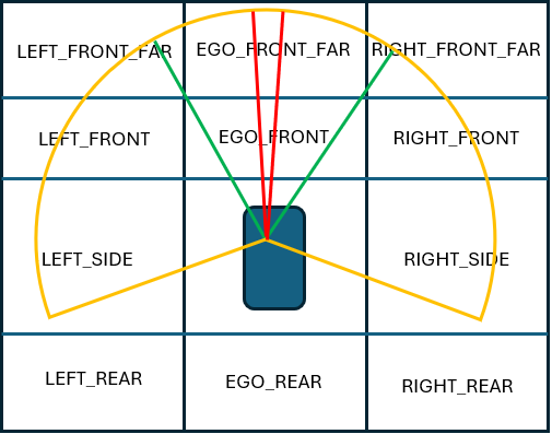
Once an AOI is fixated (and is set as the current fovea), the gaze angle is equal to its orientation. All other AOIs can be assigned to the UFOV or the periphery according to their current relative orientation. As the horizontal size of the periphery is considered as 210° and the size of the UFOV as 60° (see overview section), the assignment is done as follows:

Fig. 11 Illustrates the different areas of vision. Red is FOVEA, Green is UFOV, Yellow is Periphery. All Aois that are outside the yellow area are not perceived.
If the eccentricity of an AOI towards the gaze axis is smaller than -105° or greater than 105°, there is currently no overlap with the whole field of view and the AOI is not assigned to any of the two parts.
If the eccentricity of an AOI towards the gaze axis is greater than or equal to -105° and smaller than -30° or greater than 30° and smaller than or equal to 105°, the AOI is assigned to the periphery.
If the eccentricity of an AOI towards the gaze axis is greater than or equal to -30° and smaller than or equal to 30°, the AOI is assigned to the UFOV. This does not apply, if the AOI was already assigned as fovea, of course.
Information request mechanisms
SCM uses two different processes to determine the area the driver will focus on visually. Top-down control mechanisms of the visual attention describe cognitively driven processes which cause a gaze allocation to a specific gaze target. The opposite of top-down is called bottom-up. For Bottom-up control mechanisms, optical stimuli from the environment influence the visual attention of the driver and thus may cause a gaze allocation. Both mechanisms are described in more detail below.
Top-Down Information requests
The cognitive processes modeled in various parts of SCM decide that information about a certain AOI is required and trigger a request for it. Based on this, the model gathers the already known microscopic information for the AOI. The reliability of the information at the current time is then calculated.
The required reliability is set by the requesting module. Reliability is defined as a double value between 0 and 100 (percent) and describes the quality of mental information, based on (visual) perception or/and mental extrapolation (for a more detailed explanation, see Reliability). If the quality is lower than required, the data is not sufficient for the associated task. There are three levels of Data Quality available as pre-sets, which represent the visual perception quality at the borders between the parts of the human’s field of view (see Gaze Control). The following table shows those pre-sets.
Data Quality |
Accepted reliability |
Visual representation |
|---|---|---|
HIGH |
400/7 (about 60) |
Border between FOVEA and USEFUL_FIELD_OF_VIEW |
MEDIUM |
200/7 (about 30) |
Border between USEFUL_FIELD_OF_VIEW and PERIPHERY |
LOW |
0 |
Outer border of the PERIPHERY |
If the required reliability for an AOI is not met, an InformationRequest is sent. They consist of the following information:
Age of request
Required quality level of visual perception (fovea, UFOV, periphery)
Priority according to requesting module (i.e. priority, which is intended for information by the requesting submodule)
Priority of requesting module (e.g. priority of Detailed descriptions of situation clusters is higher than of Decision Making)
At the end of the time step, all current requests of an AOI are checked by the model. Based on the number of requests and the contained information, a score for the AOI is formed. The scores for all AreasOfInterest are aggregated and normalized with respect to the the maximum value. Then they can be used in the Gaze Control as fixation probabilities for the next gaze allocation. If the required quality for an AOI is fulfilled or exceeded by subsequent gaze movements, the requests will be removed from the AOIs again. The same applies, if the requests exceed a certain age and are not fulfilled.
Top-down control of visual attention
Top-down control mechanisms of the visual attention of the driver describe cognitively driven processes, which cause a gaze allocation to a specific gaze target. This means that the driver allocates their attention intentionally, because they may lack some information for a decision making process. For instance, the driver wants to overtake another vehicle, so they must allocate their visual attention to the neighbouring lane, especially the following vehicle in the AOI LEFT_REAR.
These processes are modelled at the end of a time step, so any intentional influence from cognitive submodules concerning e.g. lane changing wishes can be addressed in the next time step. Most of these top-down feedback loops currently consist of an overall reparameterization of probabilities and fixation durations, according to measurements from human subject studies in real world motorway driving situations. The following situations and driver’s actions are addressed by this rather implicit mechanism:
driving at slow speeds in a traffic jam
lane keeping with and without a leading vehicle
any kind of lane change actions, including preparative actions
anticipating a lane change from another vehicle on an adjacent lane (only applicable if the High Cognitive mechanism is activated)
the driver expects to be overtaken by another vehicle
the driver has not observed EGO_FRONT in a while
The only explicit mechanism currently modelled, is the specific fixation of the AOI of an adjacent lane in preparation of a lane change. This is done by allocating the gaze to only those AOIs with truly outdated information. In this case, the chance to fixate any other AOI is set 0.0 and the probability for the outdated AOI is set to 1.0, so the sampler will definitely chose this AOI as the next gaze target.
Bottom-up control of visual attention
Bottom-up control mechanisms of the visual attention of the driver describe optical impulses and stimuli from the environment, which may cause a gaze allocation. This means that the driver changes their attention unintentionally in reaction towards environmental information exposition. For instance, a vehicle is currently in the periphery of the driver’s field of view and activates its indicators. The optical stimuli of the indicators is perceived by the driver’s retina, which initiates a gaze allocation to the vehicle. Thereby, the driver can perceive the information through the fovea centralis.
These processes are modelled in GazeControl by a function which is executed before choosing the next gaze fixation. (Technically it is triggered at the end of the previous time step.) This allows a new optical stimulus from the environment to influence the behaviour in the current time step. The mechanism is not limited to other vehicles in the surrounding traffic, but also includes gaze reactions to optical and audible HMI signals (see Auditory Perception). The vehicles which are considered regarding bottom-up influences are synonymous to the AreasOfInterst EGO_FRONT, LEFT_FRONT(_FAR), and RIGHT_FRONT(_FAR).
The following stimuli are considered as bottom-up controls:
EGO_FRONT:
The object is unknown to the driver
A known object considerably closes in on the driver (tauDot <= -.5 and TTC < 5s)
LEFT_FRONT(_FAR) and RIGHT_FRONT(_FAR):
The object is unknown to the driver
Static objects
The object changes lane towards the driver
Close known object (TTC < 3s)
LEFT_SIDE and RIGHT_SIDE:
Unknown object
Known close object (TTC < 3s)
Impulses that affect the bottom-up mechanic:
EGO_FRONT:
The vehicle activates its brake lights
LEFT_FRONT(_FAR) and RIGHT_FRONT(_FAR):
The vehicle activates its brake lights (RIGHT_FRONT and LEFT_FRONT only)
The vehicle activates its indicators (RIGHT_FRONT and LEFT_FRONT only)
The mechanism addressing these stimuli firstly checks if the corresponding AOI is currently part of the useful field of view or the periphery. Please see Mapping of field of view parts to current gaze direction for further explanations on this topic. If the AOI is equal to the fovea centralis, the driver is already looking at the stimulus-emitting gaze target and there is no need for a gaze reallocation. If the AOI is not part of the whole field of view, the driver is not able to perceive the stimulus at all. In case of a match between the stimulus-emitting AOI and the not-fovea field of view, the probability for the corresponding AOI is drastically increased. The chance for a gaze allocation in the next glance is more likely then. This stochastic approach (rather than a direct feedback) takes into account that the detection of real stimuli in the real world is determined by many factors. A broader explanation is offered by Wicken’s SEEV model.
For now, SCM does not model every single possible causality derived from the real world, but is able to simulate similar driver behaviour by implementing the stochastic approach. Implementing stochastic measures thereby also means that optical stimuli can e.g. be overlooked by the driver as in real life.
Explicit control of gaze behaviour via GazeFollower
It is possible to bypass the random gaze behaviour mechanisms explained in the sections above and directly command the gaze behaviour. Thereby, the driver looks at specific AOIs at specific times. This is executed by another submodule called GazeFollower, which is triggered by the framework for a specific agent at a specific starting time.
The sequence of AOIs the agent should look at, must be defined in an external configuration file and is called a GazeTargetTimeSeries. Fig. 12 shows an example of how such a GazeTargetTimeSeries has to be defined by the user:

Fig. 12 Example for a GazeTargetTimeSeries defined by the user in the external configuration file
The time arguments state, when the associated GazeTarget is selected as the next point of gaze fixation. It is important to note that the time series is defined as relative times from the start of the GazeFollower event, so the first GazeTarget must always be defined for time equal 0. Also, the selection of the next GazeTarget does not mean that the driver can immediately look at this target, but has to execute a saccade towards this GazeTarget at first. That means, the time arguments must be considered as the start of the said saccade. The duration of this saccade is random and the remaining time until the next time series point is the actual fixation time on the GazeTarget. Fig. 13 shows how the example GazeTargetTimeSeries from Fig. 12 would be executed by the submodules GazeFollower and GazeControl, when GazeFollower is activated at 1000 ms simulation time:

Fig. 13 Execution of the example GazeTargetTimeSeries from Fig. 12 after GazeFollower activation at 1000 ms simulation time
As the last GazeTarget has no subsequent time series point, there is no designated duration for how long the driver should look at this AOI. Therefore, the duration has to be random, which states the handover moment back to the random gaze behaviour algorithm.
Besides the fact that the stated durations of GazeTargets in the GazeTargetTimeSeries consider the duration of the saccade towards this GazeTarget and the actual fixation duration of this GazeTarget, another thing that should be kept in mind when defining GazeTargetTimeSeries is the mechanism of saccadic suppression. While saccadic suppression is active, the driver is not able to visually perceive any information, so GazeTarget durations shorter than the saccade duration plus the fade-in and fade-out times of saccadic suppression will result in fixations without visual perception. In case this happens, the user is informed by a warning in the opSimulation.log (log level must be set to warning at least), but the simulation will not stop. Considering long saccades between AOI of the FRONT and REAR fields, a minimum GazeTarget duration of 250 ms should not be violated.