GPIOChip (Raspberry Pi, Beagle Bone Black and Similar Boards)
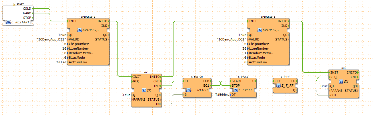
The following picture shows an example application.
The application periodically toggles the output pin 26, while the input pin 16 is high.
You can connect an LED to obtain a blinking light.
 The inputs of the GPIOChip are the following:
| Name | Description |
|---|---|
VALUE |
Receiver IX/QX block name |
ChipNumber |
ID of /dev/gpiochipX device |
LineNumber |
ID of GPIO line within the selected chip |
ReadWriteMode |
Reading/Writing mode of line (0=read, 1=write push/pull, 2=open drain, 3=open source) |
BiasMode |
Bias mode of line (0=none, 1=pull up, 2=pull down) |
ActiveLow |
True if a logic 1 corresponds to low voltage |
To find out the chip- and line number the gpioinfo tool can be used.
The VALUE input defines the IO FB to which it is connected. If the IO Block is placed inside an APP: VALUE = App-Name.FB-Name. If it is placed in the Resource: VALUE = App-Name.
Where to go from here?
You can see the supported protocols:
You can see the examples:
If you want to go back to the Where to Start page, we leave you here a fast access
Or Go to top