Module 1.4: Get started with CIF
In this course we make use of the CIF language and tools. CIF is a declarative modeling language for the specification of discrete event, timed, and hybrid systems as a collection of synchronizing automata. The CIF tooling supports the entire development process of controllers, including among others specification, supervisory controller synthesis, simulation-based validation and visualization, verification, real-time testing, and code generation. Combined, the CIF language and tools enable a synthesis-based engineering approach to efficiently and cost-effectively design and implement high-quality controllers. During this course, you will learn more about modeling with CIF, as well as how to use the CIF tools during the various steps of the development process of a supervisory controller, to develop high-quality supervisory controller in a structured way.
CIF is part of the Eclipse ESCET™ toolkit, that can be downloaded and used for free. This toolkit is developed by the Eclipse ESCET (Eclipse Supervisory Control Engineering Toolkit) open-source project. Being an open-source project at the Eclipse Foundation, the project operates in an open and transparent manner, such that anyone is free to join in and collaborate. In this sub-module, you will download the ESCET toolkit and get started with using CIF.
The Eclipse ESCET IDE
We start by downloading the ESCET toolkit. Visit the ESCET website's download page. Choose the version that matches your device's operating system and click the Download button to start the download. Follow the more detailed instructions for your operating system, a bit further down the download page, to prepare the toolkit for use. Start the Eclipse ESCET IDE, as described on the download page.
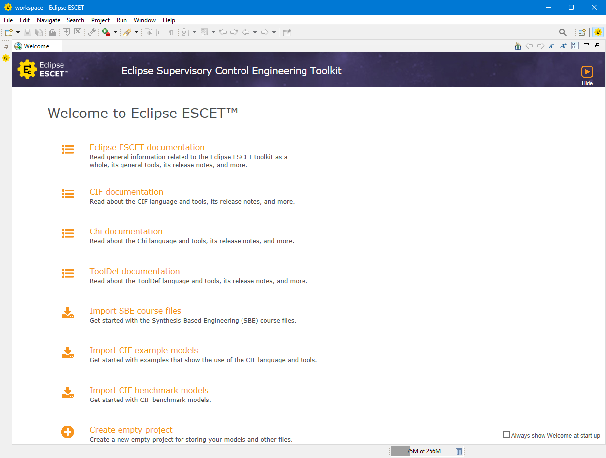
When you first start the Eclipse ESCET IDE, it asks you to select a directory for the workspace. The workspace is a folder on your computer that contains all your projects in which you store your models, scripts and other files. Once you have chosen a folder, click Launch to continue, and wait for the Eclipse ESCET IDE to appear:
If you're running Windows as your operating system and you have Windows Defender as your virus scanner, the ESCET IDE may show a dialog about Windows Defender decreasing the performance of the Eclipse IDE:
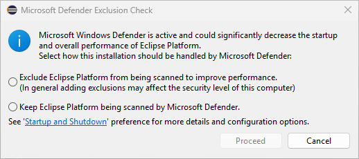
If this dialog is shown, choose to exclude the ESCET IDE from being scanned by Windows Defender if possible, provided you accept the associated risks, to ensure a smooth user experience.
From the welcome screen, you can easily access the toolkit's documentation, import example models, or create an empty project. Click the Import SBE course files link. A new window opens, where you can click Finish to complete importing the course files. Once you have completed the import, your Eclipse ESCET IDE should look something like this:
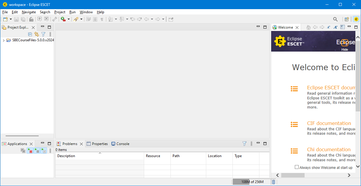
You can close the welcome screen that is now shown at the right side, by at any time by clicking the 'x' icon next to the word Welcome at the top of the welcome screen. You can reopen the welcome screen at any time by clicking the Help menu, and choosing Welcome. At the left of the Eclipse ESCET IDE, you see the Project Explorer. It shows the contents of you workspace containing all your projects. Currently, it only contains the SBE course files project, with the course files that you will use during this course. The large empty space in the middle is the working area (officially called the 'editor area'), where you will later edit your models, visualize them, and interact with them. At the bottom left, you will see which Applications are running within the Eclipse ESCET IDE. Later, you will run various tools, such as the CIF synthesis tool and the CIF simulator, and their status will be shown here. At the bottom right, various different information can be shown. For instance, any Problems that the computer detects in your models will be shown here. When a file or folder is selected in the Project Explorer, you can view its Properties, such as where is it located on your computer. And when you run certain tools, you can see the output that the tools produce on the Console.
To create a new project, open the File menu and choose New and then Project.
Enter test-project as name for the new project.
Then click Finish to create the new project.
The new project appears in the Project Explorer.
The project is still empty.
A new file can be added by right clicking the project in the Project Explorer and selecting New and then File.
Enter test-model.cif as name for the new file.
Then click Finish to create the file.
The file extension (.cif) indicates that this is a CIF file, and it will automatically be opened in the CIF text editor:
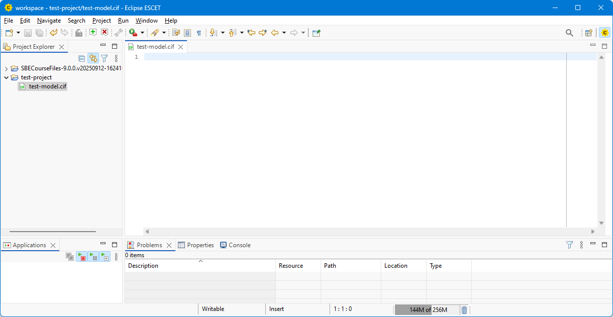
If you close the file, you can always reopen it from the Project Explorer by double clicking it. To remove a file, right click it in the Project Explorer, choose Delete, and confirm by clicking OK. You may remove the test project as well, by also right clicking it, similarly choosing Delete, selecting Delete project contents on disk, and confirming by clicking OK.
You first CIF model
To learn the basics of modeling discrete event systems in CIF, we will look at an example.
Consider a lamp that can be on or off and can change between these two states by means of the events turn_off and turn_on.
Open the project that has a name that starts with SBECourseFiles, open its module1 folder, and then double click the lamp.cif file.
You will see the following CIF model that models a lamp:
                            automaton lamp:
                                event turn_on, turn_off;

                                location on:
                                    initial;
                                    marked;
                                    edge turn_off goto off;

                                location off:
                                    edge turn_on goto on;
                            end
The model has an automaton named lamp, which represents the lamp's (discrete) behavior.
It declares two events, named turn_on and turn_off.
An event declaration only indicates that the event exists, but not yet when it can happen and what the result of that would be.
The lamp automaton has two locations, named on and off.
The lamp automaton is either in its on location, or in its off location.
The on location is the initial location of the lamp automaton.
The initial location is the active location of the automaton at the start of the system.
An automaton can have different behavior in each location, specified using edges.
An edge indicates how an automaton can change its state, by going from one location to another, and by updating the values of variables (variable updates are explained later).
In addition, edges can be associated with events to indicate what caused the state change.
The lamp automaton has an edge with the turn_off event, in its on location, going to the off location.
Whenever the lamp is on, the lamp automaton is in its on location.
Whenever the lamp is turned off, the turn_off event happens.
The edge with that event indicates what the result of that event is.
In this case, the result is that the lamp automaton will go to its off location.
The lamp automaton can go from one location to another as described by its edges, and can keep doing so.
The lamp can be turned on, off, on again, off again, etc.
This can go on forever.
The on location is a marked location.
Marking does not directly influence the behavior of the modeled system.
However, later we will synthesize supervisors from plants and requirements, and then marked locations will play an important role.
If an automaton has only one location, the name of the location may be omitted.
For edges that are self loops, that thus go to the same location as where they started from, the goto keyword and name of the target location may be omitted.
Exercise 1
Make a CIF model of the bridge deck and traffic light from the previous sub-module, with marking for a closed bridge deck and a traffic light that signals red.
                                            automaton BridgeDeck:
                                                event opened, partially_opened, closed;

                                                location Closed:
                                                    initial;
                                                    marked;
                                                    edge partially_opened goto PartiallyOpen;

                                                location PartiallyOpen:
                                                    edge opened goto Open;
                                                    edge closed goto Closed;

                                                location Open:
                                                    edge partially_opened goto PartiallyOpen;
                                            end

                                            automaton TrafficLight:
                                                event to_red, to_green;

                                                location Green:
                                                    initial;
                                                    marked;
                                                    edge to_red goto Red;

                                                location Red:
                                                    edge to_green goto Green;
                                            end
Exercise 2
Make a CIF model of the water lock's ship counter, also from the previous sub-module. Do not yet use variables, but do declare appropriate marking.
                                            automaton ShipCounter:
                                                event ship_enters, ship_leaves;

                                                location Zero:
                                                    initial;
                                                    marked;
                                                    edge ship_enters goto One;

                                                location One:
                                                    edge ship_leaves goto Zero;
                                                    edge ship_enters goto Two;

                                                location Two:
                                                    edge ship_leaves goto One;
                                                    edge ship_enters goto Three;

                                                location Three:
                                                    edge ship_leaves goto Two;
                                                    edge ship_enters goto Four;

                                                location Four:
                                                    edge ship_leaves goto Three;
                                            end
Model simulation
Congratulations, you have made your first CIF models! In this case, you were provided the correct solutions to judge whether your models were correct. Unfortunately, in practice you typically do not have the correct solution at your disposal, but you still want to validate that you made a correct model for the system. CIF has a simulator that can help to validate your model. Its interactive GUI input mode for instance allows you to interactively explore the behavior of the model. And its state visualizer allows you to observe the effect of taking transitions on the state of the system.
We will simulate the ship counter model. Before you start to simulate the model, save it by opening the File menu and choosing Save, or by using the associated keyboard shortcut. To simulate a CIF model, right click its file in the Project Explorer and choose CIF simulation, validation and verification tools and then Simulate CIF specification.... An alternative is to right click an editor where you are editing a CIF model, and choosing the same menu items. A new window opens that allows you to configure various options of the simulator. At the left you see various categories of options, and on the right you see the options of the currently selected option category. On the left, select the State visualization option category (it is part of the Output option category). Check the Visualize the state option's checkbox to enable state visualization. Click the OK button to start the simulator.
When the simulator starts, the Console is made visible at the bottom of the window. The simulator prints information about the simulation to the console, such as the states that are reached and the transitions that are taken. Besides the Console you will also see that the GUI input and State Visualizer have appeared in the editor area. The GUI input allows you to control the simulation, by clicking buttons that execute transitions for events of your system. And the effect of those transitions can be observed in the State Visualizer, which shows the current locations of all automata, and the values of all variables.
To make it easier to simulate your model, you may rearrange the various tabs in the Eclipse ESCET IDE. You may for instance make the GUI input and State Visualizer appear side by side. To move the State Visualizer to the right side, click the header of the tab that is labeled with the text State Visualizer, and while keeping the left mouse button pushed, drag the tab to the right. Once you have moved your mouse to the right side of that tab, you will see a visual indication of how the tab will be positioned:

Once you release the mouse button, the state visualizer will be moved to the right side of the window:

The State Visualizer and Console show that the ShipCounter automaton is in the Zero location.
The GUI input shows both events of the ship counter model.
The button for the ShipCounter.ship_enters event is enabled, and can be clicked.
The button for the ShipCounter.ship_leaves event is disabled, and can not be clicked.
This matches the behavior as specified in the model, for the Zero location.
Click the button for the ShipCounter.ship_enters event.
Observe how the Console shows that a transition for the event was taken, and a new state is reached where the ShipCounter is in its One location.
The new state can also be observed in the State Visualizer:
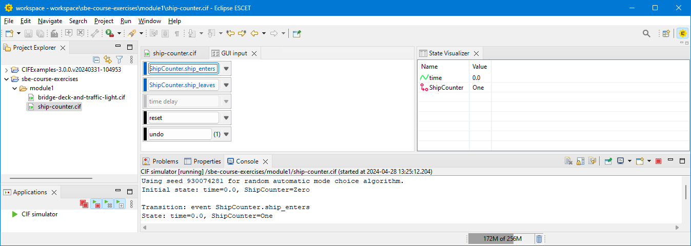
In the new state, both events are enabled. Explore the behavior of the model a bit further, by clicking buttons to take transitions, and observing the state changes. By doing so, you can check that the model exhibits the desired behavior, matching that of the system that it models.
Quiz 1
Modeling with variables
As discussed in the previous sub-module, variables can be very useful when modeling a system.
In CIF, such variables are called discrete variables and they can be declared using the disc keyword.
A discrete variables must be declared within an automaton, before its locations.
A discrete variable has a type, that indicates the possible values that the variable can have.
For instance, a variable may a boolean type (keyword bool), such that it can only have the value true or false.
Variables with an integer type (keyword int) can have integer numbers as their values.
Other types include for instance real numbers (real) and lists (such as list int).
A variable also has a name, and can be given an initial value.
If no initial value is given, the variable is initialized to the default value of its type.
For instance, a boolean variable by default gets initialized to false, an integer variable to 0, and a variable with a list type to an empty list.
Below you can see two examples of discrete variables.
The first is a boolean variable named has_product that initially has value false.
The second is an integer variable named count that initially has value 3.
                            disc bool has_product;
                            disc int count = 3;
The only way for a discrete variable to change its value, is for it to be assigned a new value by the updates of an edge within the same automaton as where the variable is declared.
The updates of an edge are indicated by the do keyword.
Updates should be written before the target location (indicated by the goto keyword).
The simplest form of update is an assignment, that starts with the name of the variable being assigned a value, followed by the 'becomes' symbol (:=), the new value, and a semicolon (;).
For instance, update do x := 7; assigns to variable x the value 7.
Guards can be used to restrict when edges may be taken.
In CIF, a guard of an edge is indicated by the when keyword, that is followed by a boolean expression.
A guard follows the event of the edge and precedes any updates.
For instance, guard when x <= 3 limits an edge to be taken only when variable x has a value that is less than or equal to 3.
By default, all values of a variable are marked.
Specific values of variables can be marked by using a marker predicate.
For instance, the marker predicate marked x < 3; can be added to an automaton (before any locations), to mark all values of variable x that are larger than 3.
As an example, consider again the lamp automaton.
Let us expand the it, by counting how many times the lamp has been turned off, with a maximum number of five times that the lamp may turn off.
The expanded model is shown below.
Note the guard when count < 5, the update do count := count + 1;, and marker predicate marked count = 0;.
                            automaton lamp:
                                event turn_on, turn_off;
                                disc int count = 0;
                                marked count = 0;

                                location on:
                                    initial;
                                    marked;
                                    edge turn_off when count < 5 do count := count + 1 goto off;

                                location off:
                                    edge turn_on goto on;
                            end
Quiz 2
Exercise 3
Make a CIF model of the water lock's ship counter from the previous sub-module, using a variables. Be sure to add proper marking.
                                            automaton ShipCounter:
                                                event ship_enters, ship_leaves;
                                                disc int count = 0;
                                                marked count = 0;

                                                location:
                                                    initial;
                                                    marked;
                                                    edge ship_enters when count < 4 do count := count + 1;
                                                    edge ship_leaves when count > 0 do count := count - 1;
                                            end