Module 4.6: Introduction to SVG visualization
Until now, if you validated your CIF model by simulating it, you used the simulator's state visualizer. This is a useful tool to quickly check whether the model is correct. However, for larger and more complex systems, it can be challenging to keep the overview of the state of the system.
To ease validation, the CIF simulator also supports SVG visualization. You have already encountered SVG visualization in the water lock case, when you simulated the water lock in the first module. SVG stands for Scalable Vector Graphics. It is an international standard for images based on vector graphics. In vector graphics, a description of a drawing is given by describing the shapes and other elements that make up the image, as well as their attributes. This contrasts it to raster images, where the image is made up of pixels. In order to display vector images on a computer screen, the description of the image is still rendered to pixels, converting the vector image to a raster image. A benefit of vector images is that they can be rendered at any resolution, and still be sharp. But, the main benefit for their use in simulation, is that we can change the attributes of the shapes and other elements, to change the image and make it reflect the current state of the system.
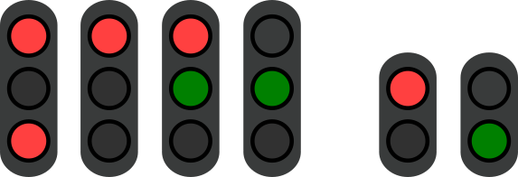
For instance, we can make an image of a traffic light, and adapt the background color of the circles of the various light during simulation, to become red and green based on the system of the system. Recall for instance the entering and leaving traffic lights that regulate water traffic of a water lock:

SVG visualization based on the state of a CIF model
SVG drawings thus consist of multiple elements which together form the drawing. Each element in the drawing can be given a unique identifier (and id). In your CIF model, you can then map the state of the CIF model to various attributes of the elements, such as colors, dimensions, positions, texts of labels, and so on.
As a very simple first example, consider a lamp that can be on or off:
                            automaton lamp:
                                event turn_on, turn_off;

                                location On:
                                    initial;
                                    marked;
                                    edge turn_off goto Off;

                                location Off:
                                    edge turn_on goto On;
                            end
The lamp automaton is either in the On location or the Off location.
We can visualize the lamp as follows, with a vector image consisting of just a circle:

The circle is given id lamp, and the SVG image is saved to an SVG file named lamp.svg.
We can then connect the SVG file to the CIF model using an SVG file declaration, and establish mappings between the CIF model and elements in the SVG image by using SVG output mappings:
                            svgfile "lamp.svg";

                            automaton lamp:
                                event turn_on, turn_off;

                                location On:
                                    initial;
                                    marked;
                                    edge turn_off goto Off;

                                location Off:
                                    edge turn_on goto On;

                                svgout id "lamp" attr "fill" value if Off: "silver" else "yellow" end;
                            end
The CIF model now has an svgfile declaration at the top, indicating that the lamp.svg file is to be connected to this CIF model.
In this case, the SVG file is in the same folder as the CIF model, and therefore just the SVG file name is indicated.
If the SVG file would be in a sub-folder named images, you'd use svgfile "images/lamp.svg";.
The CIF model now also has an SVG output mapping, indicated by svgout.
It specifies that the element named lamp in the SVG image has an attribute named fill, and that the value of this attribute is to be updated based on the state of the CIF model.
The fill attribute of a circle determines its fill color.
In this case, if the automaton is in the Off location, the fill color is silver, and otherwise it is yellow.
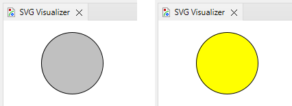
The result is that the circle is either silver or yellow, depending on the current location of the automaton:

In general, an SVG output mapping that changes the value of an attribute of an SVG element, requires the id of that element, the name of one of its attributes, and an expression that determines the value of the attribute. The id can be given as just its name, but we can for instance also compute the id:
                            svgfile "lamp2.svg";

                            automaton def Lamp(alg int nr):
                                event turn_on, turn_off;

                                location On:
                                    initial;
                                    marked;
                                    edge turn_off goto Off;

                                location Off:
                                    edge turn_on goto On;

                                svgout id "lamp" + <string>nr attr "fill" value if Off: "silver" else "yellow" end;
                            end

                            lamp1: Lamp(1);
                            lamp2: Lamp(2);
The lamp automaton is now an automaton definition named Lamp, with a parameter nr.
It is instantiated twice, once with value 1 and once with value 2.
The SVG output mapping uses the parameter to map to either the element with id lamp1 or the one with id lamp2.
It does so, by adding to the text lamp the value of nr as text, which is obtained through a conversion of the number to the string data type that is used to represent text.
For the value, we here used an if expression.
It can produce different values depending on the state of the model.
In this case, based on whether the automaton is in location Off or not.
You can read more about if expressions, as well as about the related concept of switch expressions, in the CIF tutorial, specifically the lesson on if and switch expressions.
If you simulate a model that is connected to an SVG image, the CIF simulator will automatically open the SVG visualizer. The SVG image is then automatically updated during the simulation, based on the state of the system, as shown above for the lamp being silver or yellow.
To learn more about SVG visualization, check out the CIF documentation. It includes information about tools to create and edit SVG images, about SVG output mappings, about how to not only change shapes but also text, and so on. It also includes several examples.
Interactive simulation using SVG images
So far, we have used the state of the model as output from the model to have it be reflected in the SVG image. But, it is also possible to have them influence each other the other way around, by having the image affect the model. That is, it is possible make mappings that specify that clicking on certain elements in the image affects the behavior of the model during simulation.
For this, CIF features SVG input mappings. With an SVG input mapping, you can map an element of an SVG image and define which event should be enabled in the model when it is clicked. Such an interactive SVG event is then disabled as long as the element in the image is not clicked, and only once it is clicked does the event become enabled. The event can then be taken just once, after which it becomes disabled again until an element of the image that enables it is clicked.
As an example, consider the following model of the lamp above, extended with a button.
For as long as the button keeps being pushed, the lamp is on, but once the button is released, the lamp goes off again.
We can make an SVG image for it, and save it as button_lamp.svg:

It still has the lamp, but now also a button. We can make the following model for it:
                            svgfile "button_lamp.svg";

                            plant button:
                                uncontrollable u_pushed, u_released;

                                location Released:
                                    initial;
                                    marked;
                                    edge u_pushed goto Pushed;

                                location Pushed:
                                    edge u_released goto Released;

                                svgout id "button" attr "width" value if Pushed: 12 else 36 end;
                            end

                            plant lamp:
                                controllable c_on, c_off;

                                location Off:
                                    initial;
                                    marked;
                                    edge c_on goto On;

                                location On:
                                    edge c_off goto Off;

                                svgout id "lamp" attr "fill" value if Off: "silver" else "yellow" end;
                            end

                            supervisor controller:
                                location:
                                    initial;
                                    marked;
                                    edge lamp.c_on when button.Pushed;
                                    edge lamp.c_off when button.Released;
                            end

                            svgin id "button" event if   button.Released: button.u_pushed
                                                    elif button.Pushed:   button.u_released
                                                    end;
The SVG input mapping indicates that if the SVG element with id button is clicked, and the button automaton is in its Released location, then the u_pushed event is enabled.
If the automaton is instead in its Pushed location, then the u_released event is enabled.
It is however also possible to simply list a single event, instead of the whole if, and then this single event is enabled whenever the SVG element is clicked.
To learn more about SVG interaction and SVG input mappings, check out the CIF documentation.
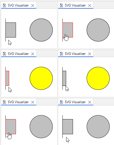
To enable SVG interaction, you should configure the CIF simulator's Input mode option, in the Input category to SVG input mode. If we simulate this example model, and regularly press the button, the result is something like this:

When hovering over an interactive element, it gets highlighted with a red border. When clicking it, it briefly gets a green border. To learn more about the CIF simulator's SVG input mode, check out the CIF documentation.
Simulation in a browser
The CIF simulator can be used to simulate a model interactively, through SVG visualization and interaction. Sometimes, you want to share your model with others, such that they can also simulate it. For instance, to have others review whether the controlled system operates as envisioned, and no requirements were missed.
Allowing others to simulate your model requires sharing all relevant files, including not only the CIF model file itself, but also its imported other CIF files and its connected SVG images. Besides that, the other people then need to install the ESCET tooling, which includes the CIF simulator. This may not be desired in all situations. For instance, a person making a controller for a bridge may want to ask a bridge operator for feedback, but a bridge operator may not be used to work with tooling like Eclipse ESCET. Furthermore, some companies disallow installing non-approved software on their systems.
An alternative way to simulate a CIF model, that addresses these concerns, is to simulate it in a browser. To simulate a model in a browser, you first use the CIF code generator to generate a single HTML file from a model and its visualizations. Then, the generated HTML file can be opened in any modern web browser, allowing you to interactively simulate your model without requiring Eclipse ESCET to be available. Since everything that is needed for simulation is contained in a single file, it is also easy to share such a file with others, for instance as an email attachment.
Simulation in the browser is more limited than simulation using the CIF simulator. Use simulation in a browser when sharing the model with less technical users. In other situations, it is recommended to use the CIF simulator, as it has more options to configure the simulation.
To generate an HTML file from a CIF model, right click the .cif file in the Project Explorer, and choose CIF implementation tools and then Generate code for CIF specification....
Since generating an HTML file is the default, it suffices to accept the default options and click OK.
Wait for the code generator to have written the .html file.
Then double click that generated .html file to open it in your browser.
In the browser, you can interact with the SVG image as you would in the CIF simulator.
For more information, see the CIF code generator documentation.
Quiz
svgin id {id name} event {event name};",
"svgin id {event name} event {id name};",
"svgout id {id name} attr {attr name} value if {expression}: {value when true} else {value when false} end;",
"svgin id {id name} attr {attr name} value if {expression}: {value when true} else {value when false} end;"
],
correctAnswer: '1'
},
{
type: 'single-choice',
question: "What is a correct structure of an SVG output mapping?",
answers: [
"svgout id {id name} event {event name};",
"svgin id {event name} event {id name};",
"svgout id {id name} attr {attr name} value if {expression}: {value when true} else {value when false} end;",
"svgin id {id name} attr {attr name} value if {expression}: {value when true} else {value when false} end;"
],
correctAnswer: '3'
},
{
type: 'single-choice',
question: "How is an SVG image connected to the CIF model containing the mappings?",
answers: [
"By right-clicking the CIF file, starting the simulation and in the option dialog typing in the path to the SVG image.",
"By typing svgfile with the path to the SVG file in the CIF model.",
"By typing ciffile with the path to the SVG file in the SVG image."
],
correctAnswer: '2'
}
]