Module 2.8: Exercises
You will now practice what you have learned in this second module. When modeling, there is generally not one correct answer, as multiple solutions are possible. After you complete an exercise, an example solution is given, together with an explanation.
Exercise 1
Consider again the example model with a bridge deck, bridge light and car, from the constants and algebraic variables sub-module. Compute the state space of the model using the CIF explorer. Visualize the state space by converted the state space CIF model to a yEd model diagram, opening it in yEd, and applying One-Click Layout. Why does the state space have 20 states and 56 transitions?
The angle of the bridge deck can vary between 0 and 90 degrees, for a total of 10 different angles. The bridge light can be either on or off. These can be combined in any combination, so there are 10 * 2 = 20 states.
From most states, it is possible to both open the bridge deck further and close it further. From all states, it is possible to either turn the bridge on or off. For most states, there are thus three possible transitions. There are a few states that are exceptional in this regard. For the states where the bridge deck is fully open, it is not possible for the bridge deck to be opened any further. Similarly, for the states where the bridge deck is fully closed, it is not possible for the bridge deck to be closed any further. In total there are four states with only two transitions, namely those where the bridge deck is fully opened or closed, in combination with the bridge light being either on or off. This means that there are thus (20 * 3) - 4 = 56 transitions.
You may have noticed that the state space model has groups. Groups can be used to group automata, event declarations and so on, bringing structure to a model. In this case, the groups are used to preserve the structure of the original model. The original automata are replaced by groups, such that the events declared inside of them are still grouped as in the original model. To refer to an event declared in a group, from outside that group, the event name needs to be prefixed with the name of the group and a period, like when referring to an event declared in an automaton from outside that automaton. Groups are further explained later in the course.
Exercise 2
Consider again the example model with a bridge deck, bridge light and car. Check again the state space or simulate the model.
a. Does the model have any unsafe behavior?
Hint: Consider whether all transitions are desired.
Yes, the model has unsafe behavior. The bridge deck and bridge light operate independently. They don't synchronize on any events, nor do they share any variables. The bridge deck can therefore be opened, while the bridge light is off.
The car_may_drive and car_may_not_drive variables correctly indicate whether the car may or may not drive.
But, what happens when the driver is not paying attention to whether to bridge deck is open or closed, and only looks at the bridge light?
In that case, the car would drive into the water.
It would be safer if the bridge light were always on when the bridge deck is not fully closed.
So, all states where the bridge deck is not fully closed and the bridge light is off should not be reachable.
b. Change the model to make it safe, by adding guards to the relevant edges.
The bridge light must be on for the bridge deck to be opened. Furthermore, the bridge light should only be turned off when the bridge is fully closed. Below is an example of how of how the model can be made safe.
The open_further and close_further edges are guarded with the bridge light being on, to ensure the bridge deck does not move when the bridge light is off.
Instead of using the location in the guard, we could have also opted for the algebraic boolean variable is_on.
The turn_off event is guarded with the bridge deck being closed.
Here too, we used the algebraic variable, rather than directly using angle, since this gives better abstraction and leads to a more readable model.
                                            automaton bridge_deck:
                                                disc int angle = 0;
                                                event open_further, close_further;

                                                const int step = 10;

                                                alg bool is_open   = angle >= 90;
                                                alg bool is_closed = angle <= 0;

                                                location:
                                                    initial;
                                                    edge open_further  when angle < 90 and bridge_light.On do angle := angle + step;
                                                    edge close_further when angle >  0 and bridge_light.On do angle := angle - step;
                                            end

                                            automaton bridge_light:
                                                event turn_on, turn_off;

                                                alg bool is_on = On;
                                                alg bool is_off = Off;

                                                location On:
                                                    initial;
                                                    edge turn_off when bridge_deck.is_closed goto Off;

                                                location Off:
                                                    edge turn_on goto On;
                                            end

                                            alg bool car_may_drive     =     bridge_deck.is_closed and bridge_light.is_off;
                                            alg bool car_may_not_drive = not bridge_deck.is_closed or  bridge_light.is_on;
Exercise 3
Compute the state space of some examples manually, without using any tools, such as the CIF explorer.
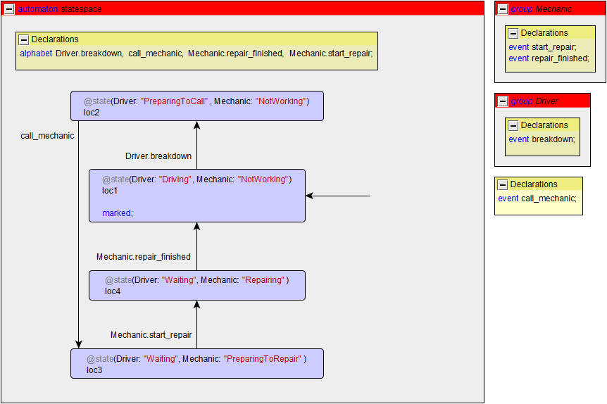
a. Compute the state space of the driver and mechanic example from the synchronizing automata sub-module.

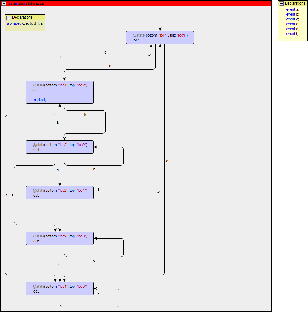
b. Compute the state space of the two-automata example from the quiz of the synchronizing automata sub-module.

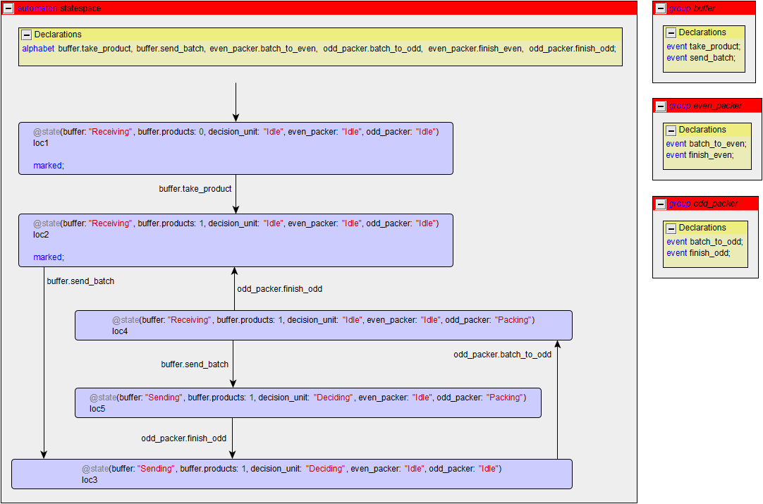
c. Compute the state space of the production line from the shared variables sub-module, with at most one product in the system, and any non-empty batch is allowed to be sent.

Exercise 4
Consider the models for which you computed the state spaces in exercises 3a and 3b. Answer for both of them the following questions:
- Are there any deadlock states?
- Are all the locations of the automata reachable?
- Is the state space non-blocking?
For the solution to exercise 3a:
- No, there are no deadlock states, as every reachable state has an outgoing transition.
- Yes, since all three locations of
Driverand all three locations ofMechanicare reachable. - Yes, since the initial state is marked, and it is always possible to get back to the initial state.
For the solution to exercise 3b:
- No, there are no deadlock states, as every reachable state has an outgoing transition, including
loc3, which has a self loop transition. - Yes, since all three locations of the top automaton and both locations of the bottom automaton are reachable.
-
No.
The
loc3is not marked, and since it only has a self loop transition, no marked state can be reached from it. Furthermore,loc6is also not marked, and from it only the state itself (via a self loop) andloc3(via a transition for eventa), can be reached. Neither of these two states is marked. Since there are two states,loc3andloc6that are not marked and from which no marked state can be reached, the model is blocking.
Exercise 5
Consider again the product line from the shared variables sub-module. Make a CIF model for it. Check that it has the correct behavior, using simulation and by computing and visualizing the state space.
                                            automaton buffer:
                                                event take_product, send_batch;
                                                disc int products = 0;

                                                location Receiving:
                                                    initial;
                                                    marked;
                                                    edge take_product when products < 10 do products := products + 1;
                                                    edge send_batch when products > 4 goto Sending;

                                                location Sending:
                                                    edge even_packer.batch_to_even, odd_packer.batch_to_odd goto Receiving;
                                            end

                                            automaton decision_unit:
                                                location Idle:
                                                    initial;
                                                    marked;
                                                    edge buffer.send_batch goto Deciding;

                                                location Deciding:
                                                    edge even_packer.batch_to_even when buffer.products mod 2 = 0 goto Idle;
                                                    edge odd_packer.batch_to_odd when buffer.products mod 2 = 1 goto Idle;
                                            end

                                            automaton even_packer:
                                                event batch_to_even, finish_even;

                                                location Idle:
                                                    initial;
                                                    marked;
                                                    edge batch_to_even goto Packing;

                                                location Packing:
                                                    edge finish_even goto Idle;
                                            end

                                            automaton odd_packer:
                                                event batch_to_odd, finish_odd;

                                                location Idle:
                                                    initial;
                                                    marked;
                                                    edge batch_to_odd goto Packing;

                                                location Packing:
                                                    edge finish_odd goto Idle;
                                            end
Exercise 6
Consider again exercise 4 from the exercises of Module 1. When you look at the solution of that exercise, you can now recognize that it is actually the state space of a model with two automata. You can see this most prominently by the fact that the locations are named as pairs consisting of the names of the current locations of the two automata.
Identify the two automata for which the solution is the state space. Model the two automata as a CIF model, without using variables. Check that the behavior of your CIF model is the same as the state space that is given as the solution in exercise 4 of Module 1. Also check the behavior against the model that you made in exercise 8 of Module 1, where you modeled the single automaton in CIF, and make sure it is the same.
                                            automaton lamp:
                                                event turn_on, turn_off;

                                                location Off:
                                                    initial;
                                                    marked;
                                                    edge turn_on when counter.Zero or counter.Two or counter.Four goto On;

                                                location On:
                                                    edge turn_off goto Off;
                                            end

                                            automaton counter:
                                                event increment, decrement;

                                                location Zero:
                                                    initial;
                                                    marked;
                                                    edge increment when lamp.Off goto One;

                                                location One:
                                                    edge decrement goto Zero;
                                                    edge increment goto Two;

                                                location Two:
                                                    edge decrement when lamp.Off goto One;
                                                    edge increment when lamp.Off goto Three;

                                                location Three:
                                                    edge decrement goto Two;
                                                    edge increment goto Four;

                                                location Four:
                                                    edge decrement when lamp.Off goto Three;
                                            end
Exercise 7
You will model the interaction between two hay balers and a bale loader.
A hay baler is a farming machine that makes square or round bales, depending on the type, of hay or straw.
A baler makes a bale on event make_bale and has a counter that counts how many bales have been made so far (variable name bales).
The two balers are identical and work independently of each other.
The bale loader is a machine that loads the bales and brings them to the farm.
It has a capacity of 10 bales and only collects them when enough bales are present.
Collecting the 10 bales, by event load_bales, can be modeled as happening instantaneously when enough bales are present on the field.
The bale loader also has a counter that keeps track of how many bales have been loaded so far (variable name loaded_bales).
a. Model this system in CIF using multiple automata.
Keep the following in mind:
- The load capacity of the loader should be easily adjustable.
- Define an integer variable named
bales_on_fieldthat automatically keeps track of the number of bales still on the field. - Define a boolean variable that automatically indicates to the loader whether enough bales are on the field to start loading.
The balers each have their own make_bale event, to make sure they operate independently.
These events belong logically to the balers, and are thus defined locally.
The balers can make bales, increasing the amount of bales they've made by one.
The bale loader has a constant to define its capacity, allowing it to be easily changed.
This constant is placed in the bale_loader automaton, as it indicates a property of the bale loader.
Similarly to how the balers count the number of bales they've made, the loader counts the number of bales its loaded.
Algebraic variable bales_on_field counts the number of bales on the field, as the different between the baled bales and the loaded bales.
This variable is defined globally, since it relates to both balers and bale loader and the field that they share, rather than any one of them in particular.
The loader uses the bales_on_field variable to define enough_bales that indicates whether enough bales are on the field to load the loader to capacity.
This variable is also defined locally for the bale loader, as it indicates a condition for the bale loader, and it is used only by the bale loader.
The edge for the load_bales event is guarded with this variable to ensure that the loader operates correctly.
                                            alg int bales_on_field = baler1.bales + baler2.bales - bale_loader.loaded_bales;

                                            automaton baler1:
                                                event make_bale;
                                                disc int bales = 0;

                                                location:
                                                    initial;
                                                    marked;
                                                    edge make_bale do bales := bales + 1;
                                            end

                                            automaton baler2:
                                                event make_bale;
                                                disc int bales = 0;

                                                location:
                                                    initial;
                                                    marked;
                                                    edge make_bale do bales := bales + 1;
                                            end

                                            automaton bale_loader:
                                                event load_bales;
                                                disc int loaded_bales = 0;

                                                const int load_capacity = 10;
                                                alg bool enough_bales = bales_on_field >= load_capacity;

                                                location:
                                                    initial;
                                                    marked;
                                                    edge load_bales when enough_bales do loaded_bales := loaded_bales + load_capacity;
                                            end
b. Adapt the model to make sure the loader can keep up with the balers.
Let's assume that the loader cannot keep up with the balers. Therefore, it tells them to stop when they have baled enough bales to meet its load capacity. The balers can only restart baling when the loader has loaded its bales.
Add an event stop_baling that informs both balers to stop baling.
Do not introduce any other new events.
We introduce event stop_bailing outside the automata, as it is shared by multiple balers and the bale loader.
Alternatively, we could have placed it in the bale loader, since it initiates the event, telling the bale loaders to stop baling.
The bale loader requires the event to take place only when enough bales have been baled.
The balers synchronize on the event and go to a different location, where they do not bale any more bales.
Once the loader has loaded the bales, through event load_bales, the balers go back to their bailing location to continue bailing.
To make sure that the balers do not make more bales when enough bales have been made for the loader to start loading, extra guards are added to the edges for the make_bale event.
                                            alg int bales_on_field = baler1.bales + baler2.bales - bale_loader.loaded_bales;

                                            event stop_baling;

                                            automaton baler1:
                                                event make_bale;
                                                disc int bales = 0;

                                                location Baling:
                                                    initial;
                                                    marked;
                                                    edge make_bale when not bale_loader.enough_bales do bales := bales + 1;
                                                    edge stop_baling goto NotBaling;

                                                location NotBaling:
                                                    edge bale_loader.load_bales goto Baling;
                                            end

                                            automaton baler2:
                                                event make_bale;
                                                disc int bales = 0;

                                                location Baling:
                                                    initial;
                                                    marked;
                                                    edge make_bale when not bale_loader.enough_bales do bales := bales + 1;
                                                    edge stop_baling goto NotBaling;

                                                location NotBaling:
                                                    edge bale_loader.load_bales goto Baling;
                                            end

                                            automaton bale_loader:
                                                event load_bales;
                                                disc int loaded_bales = 0;

                                                const int load_capacity = 10;
                                                alg bool enough_bales = bales_on_field >= load_capacity;

                                                location:
                                                    initial;
                                                    marked;
                                                    edge load_bales  when enough_bales do loaded_bales := loaded_bales + load_capacity;
                                                    edge stop_baling when enough_bales;
                                            end