Module 1.6: Introduction to the water lock case
During this course, you will work on a concrete case, to practice what you have learned. In the case, you will develop a supervisory controller for a water lock. As you learn more about synthesis-based engineering in the various modules, you will apply what you have learned to this case, at the end of each module. That way, by the end of the course you will have modeled the plants and requirements, synthesized a supervisory, and validated it through simulation.
In this module, the water lock case is introduced. Furthermore, you will start to model the water lock using automata, as you already practiced earlier in this module.
Water lock
The end product of the water lock case is a synthesized supervisory controller of a simplified version of the Westsluis, one of the locks of the Terneuzen lock complex in the Netherlands:
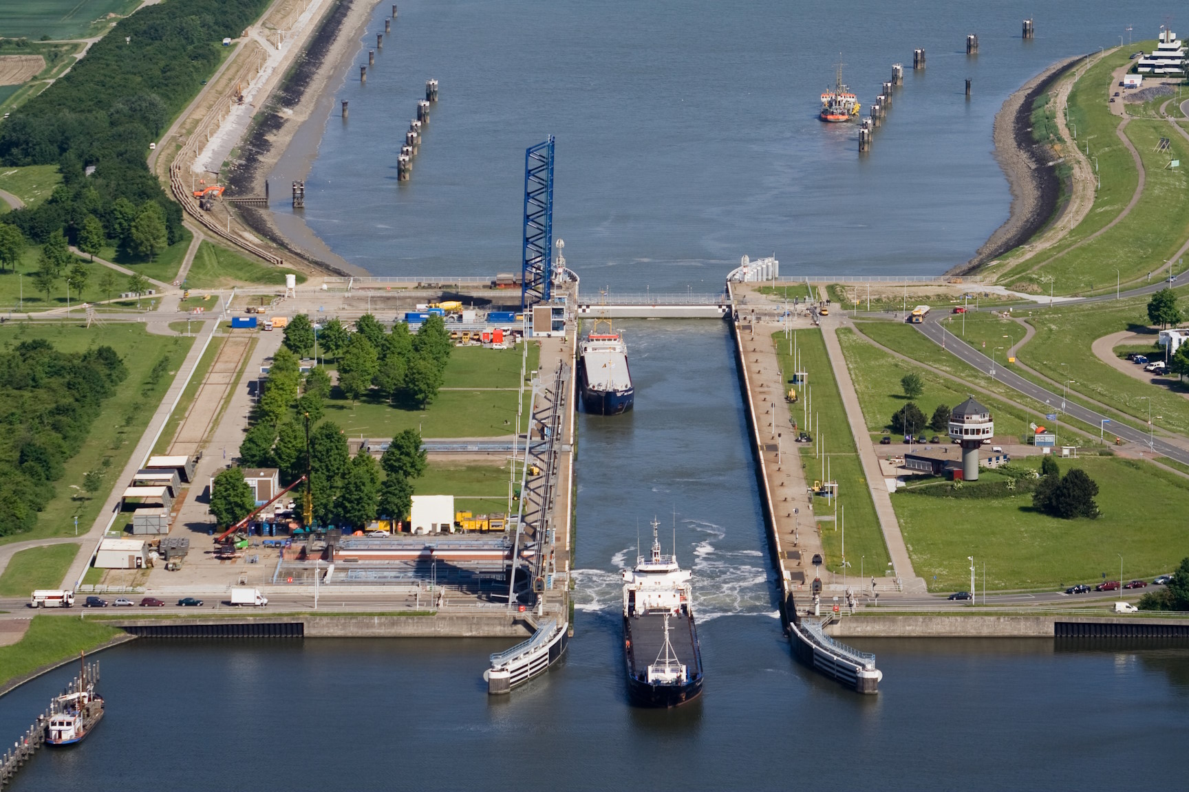
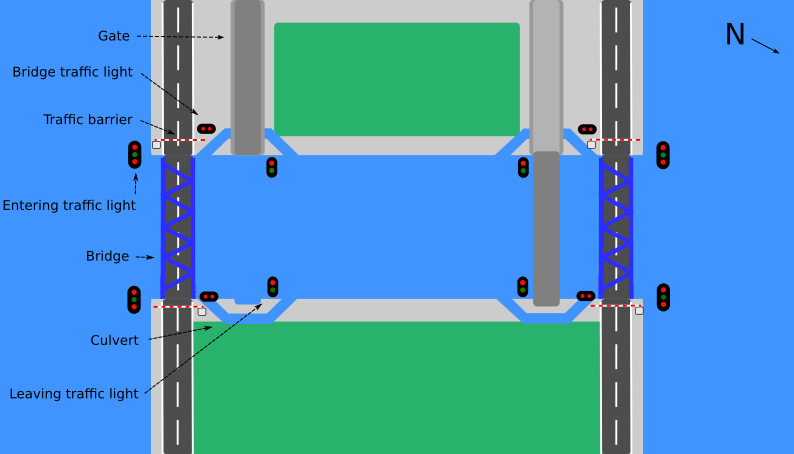
The Westsluis consists of 5 sliding gates, two at each end and one in the middle. In this course, we consider a simplified version of the lock with only two gates, one at each end. The other components of the Westsluis are two bridges with traffic barriers and traffic lights (horizontal with two lights) at each end, two pairs of culverts responsible for filling and draining the chamber, two pairs of entering traffic lights (vertical with three lights) and two pairs of leaving traffic lights (vertical with two lights). The traffic lights will be discussed in more detail below. The following figure shows a schematic overview of the Westsluis. The arrow labeled with 'N' indicates which direction is north:
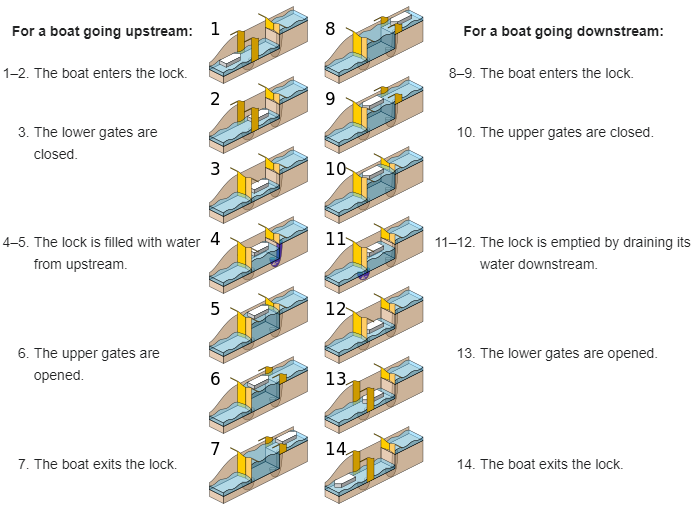
A water lock's function is to raise or lower boats, ships and other watercraft between stretches of water with different levels on rivers or canal waterways. A minimum of two gates is needed that maintain the different water levels and create a chamber between them. This chamber can be filled with water to raise a watercraft, or drained to lower a watercraft. To raise the water level in the chamber, the culverts that connect the chamber with the upstream water (higher water level) are opened. Gravity makes the water flow into the chamber. Once the water level is the same as upstream, the upstream gate is opened and the watercraft can proceed into the lock. The upstream gate is then closed, before the culverts that connect the chamber with the downstream water (lower water level) are opened to lower the water in the chamber. Gravity makes the water flow out of the chamber. Once the water level is the same as downstream, the downstream gate is opened and the watercraft can leave the lock to continue its journey. The following figure shows the operation of a water lock:
The Westsluis has bridges over which road traffic can pass. This traffic is regulated with traffic barriers and traffic lights. These traffic lights consist of two red lights positioned next to each other horizontally. The two red lights alternate being on and off when the traffic light is on, such that always one is on and the other is off. The time interval between two alternations of the red lights is fixed. When the traffic light is off, both lights are off. The following figure shows the two alternating states of a bridge traffic light that is on:

Each water lock has entering and leaving lights that regulate the water traffic. The entering lights consist from top to bottom of a red, green and red light. With these three lights, four signals are communicated to vessels waiting to enter the lock: red/red, red, red/green and green, as shown below. The leaving lights consist of a red light at the top and a green one at the bottom, which are used to give two signals: red and green, as also shown below:
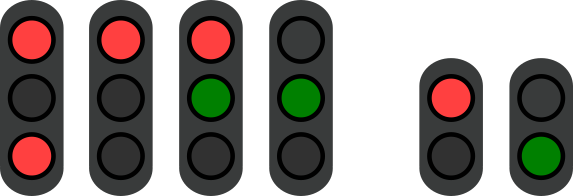
From left to right, these 6 signals indicate:
- Red/Red: The water lock is out of service. Do not enter.
- Red: Sailing in prohibited. Do not enter.
- Red/Green: Prepare for sailing in. Wait to enter.
- Green: Sailing in allowed. Enter now.
- Red: Sailing out prohibited. Do not leave.
- Green: Sailing out allowed. Leave now.
Simulation model
To get familiar with the functioning of the water lock, a simulation model is provided as part of the course files that you imported earlier. The simulation model comes with a visualization of the water lock, closely resembling that of the schematic overview of the water lock as shown above. During the simulation, the visualization is updated to reflect the state of the water lock. This is often more intuitive than the state visualizer we used earlier. Besides visualizing the current state of the system, the visualization also allows for interaction with the system. You can click on a component in the visualization to show a window with commands for that component. Once you click on a command, the associated event occurs in the model, leading to changes in the system's state, which will then be shown again in the visualization. The visualization thus also acts as a user interface for the system during simulation. Visualizations and interaction through visualizations are discussed in more detail later in the course.
In the course files project, in the module1 folder, there is a folder named water-lock.
In that folder are several files that together comprise the simulation model.
Do not try to understand how these files are constructed, as they use numerous concepts that are only introduced later in the course.
The following files are present:
-
lock.cif: This file contains the model of the Westsluis water lock. It models all of the lock's behavior, including behavior that is dangerous or not allowed. -
lock.svg: The file contains a vector drawing of the water lock, used to visualize the water lock's state. A vector drawing consists of various shapes and text labels and their associated properties, such as dimensions, positions, colors, and so on. -
simulation.cif: This file contains the simulation model of the water lock. It connects the state of the water lock model to properties of the vector drawing, such that if the state of the model changes the drawing can also be updated. For instance, if in the water lock model a light is turned on, the corresponding shape in the drawing may get a green color. The simulation model also connects clicks on interactive elements of the vector drawing to events in the water lock model. -
simulate.tooldef: This file contains a script to simulate the water lock. Executing the script starts the simulator with the proper configuration to simulate the water lock interactively.
To execute the script, select it in the Project Explorer and then press the F10 key on you keyboard. Alternatively, right click the file and choose Execute ToolDef. Once the simulation starts, the visualization is shown. When you hover your mouse pointer over an interactive element of the drawing, that element is highlighted with a red border and your mouse pointer changes shape. As previously mentioned, clicking an interactive component of the system opens a popup window with commands that can be given to the system to control the particular component. A popup window can be closed by clicking the 'x' at the top right of that popup window.
Go ahead and simulate the water lock, to discover its behavior. Then proceed to the assignments below.
Assignment 1
Using simulation, try to find any dangerous behavior of the water lock. What is the dangerous behavior?
By simulating the water lock, you hopefully concluded that this is not a safe system yet. The lock now consists of the components that act independently of the state of the other components. When you allow a human operator to operate this system, dangerous situations are bound to happen in the long run because of human error or malevolence.
If the operator, for example, per accident, opens the bridge without closing the traffic barriers first, cars can still be on the bridge, or arriving cars can drive into the water. A correct supervisory controller prevents this from happening, as it will disable the possibility of opening the bridge when the traffic barriers are not yet closed. If the operator then wants to open the bridge, the supervisory controller will prohibit this, and nothing happens.
Furthermore, both gates can be opened at the same, as can both culverts. Doing so will lead to a flood. A correct supervisory controller, as you will develop during this course, will prevent that.
Assignment 2
In this module, you learned how to use automata to create a plant model for a system. Now you will apply this knowledge to create a plant model for the water lock. While it is possible to make a single automaton of the entire water lock, this model would be unnecessarily large and complex. Therefore, it is easier to model each component of the water lock separately, using much smaller automata.
Write down the components that comprise the water lock. Can these components also be divided into groups?
The lock consists of the following components, where the letters N, E, S and W are short for North, East, South and West:
- Gate N, Gate S.
- Bridge N, Bridge S.
- Culvert NW, Culvert NE, Culvert SW, Culvert SE.
- Traffic barrier NW, Traffic barrier NE, Traffic barrier SW, Traffic barrier SE.
- Entering lights NW, Entering lights NE, Entering lights SW, Entering lights SE.
- Leaving lights NW, Leaving lights NE, Leaving lights SW, Leaving lights SE.
- Traffic lights NW, Traffic lights NE, Traffic lights SW, Traffic lights SE.
These components can be grouped in multiple ways. One way is shown in the figure below:
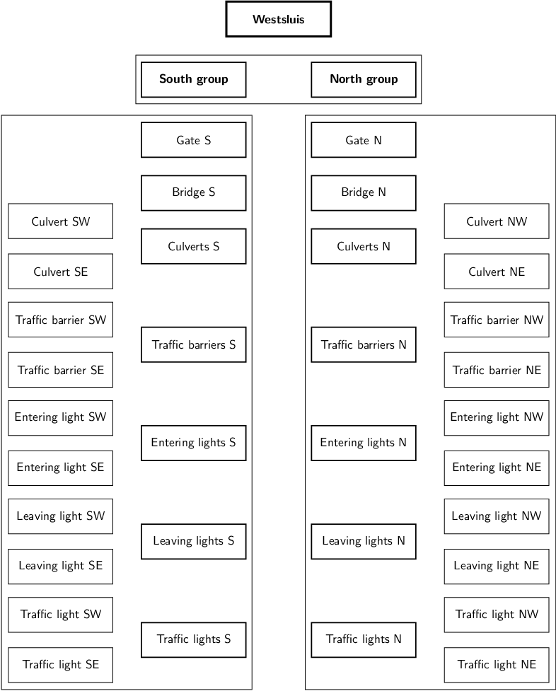
As the system is fully symmetrical, it is convenient to divide it into a North group and a South group. Once the North group is modeled, the South group can be modeled similarly. By copying the North group part of the model and reusing it for the South group, modeling the South group then takes much less effort. Within each group, it is convenient to group the components of the same kind. So the traffic lights are kept together, as are the culverts, entering lights and leaving lights.
Assignment 3
We now have a good overview of the system. The system has seven types of components: gates, bridges, culverts, traffic barriers, entering lights, leaving lights and traffic lights. As explained earlier, to perform synthesis we need to create a plant model with all possible behavior of the system, before adding the requirements to restrict that behavior.
Create a discrete event model of the water lock, with one automaton for each type of component of the water lock. So, for instance, do not yet model each traffic light. A single traffic light automaton is sufficient for now, as all other traffic lights will be similar. Do think of appropriate events, locations and edges. Also consider which locations should be initial or marked.
Once you have modeled the seven automata, do you see similarities between the automata? Can you make an automaton that can represent multiple types of components?
The gates, culverts, traffic barriers and bridges are all similar components, when considering how they can be modeled as automata.
They can all be open or closed.
Therefore, they can all be represented by a single OpenClosedComponent automaton.
In a later module, you will learn how to define an automaton definition and instantiate it multiple times, once for each gate, culvert, traffic light and bridge.
A leaving traffic light and bridge traffic light could also be seen as similar, as they too have two states and edges between them. However, we will see in the next module that they are different in other ways.
                                            automaton OpenClosedComponent:
                                                event to_open, to_closed;

                                                location Closed:
                                                    marked; initial;
                                                    edge to_open   goto Open;

                                                location Open:
                                                    edge to_closed goto Closed;
                                            end

                                            automaton EnteringTrafficLight:
                                                event to_red_red, to_red, to_red_green, to_green;

                                                location Red:
                                                    initial;
                                                    marked;
                                                    edge to_red_red   goto RedRed;
                                                    edge to_red_green goto RedGreen;
                                                    edge to_green     goto Green;

                                                location RedRed:
                                                    marked;
                                                    edge to_red       goto Red;
                                                    edge to_red_green goto RedGreen;
                                                    edge to_green     goto Green;

                                                location RedGreen:
                                                    edge to_red       goto Red;
                                                    edge to_red_red   goto RedRed;
                                                    edge to_green     goto Green;

                                                location Green:
                                                    edge to_red       goto Red;
                                                    edge to_red_red   goto RedRed;
                                                    edge to_red_green goto RedGreen;
                                            end

                                            automaton LeavingTrafficLight:
                                                event to_green, to_red;

                                                location Red:
                                                    initial;
                                                    marked;
                                                    edge to_green goto Green;

                                                location Green:
                                                    edge to_red   goto Red;
                                            end

                                            automaton BridgeTrafficLight:
                                                event to_on, to_off;

                                                location Off:
                                                    initial;
                                                    marked;
                                                    edge to_on  goto On;

                                                location On:
                                                    edge to_off goto Off;
                                            end