Tank example
This example shows:
Use of the
scalestandard library function.How inverting the y-axis can reduce the number of output mappings.
SVG image
The following SVG image is used for this example:
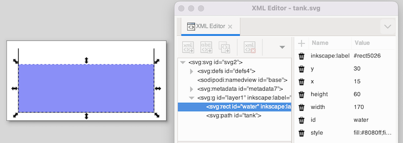
The image features a tank (black lines) and the water in the tank (blue rectangle). The water rectangle is selected. In the XML Editor window, you see the position as SVG represents it. It shows 15 for the x position and 30 for the y position. These values are relative to the upper left corner of the canvas.
CIF specification
The following CIF specification models the tank example:
// Behavior.
const real CAPACITY   = 10.0;
const real MAX_LEVEL  =  8.0;
const real INIT_LEVEL =  5.0;
const real MIN_LEVEL  =  2.0;

automaton tank:
  cont level = INIT_LEVEL;

  location open:
    initial;
    equation level' =  1.0;
    edge when level >= MAX_LEVEL goto closed;

  location closed:
    equation level' = -1.0;
    edge when level <= MIN_LEVEL goto open;
end

// Visualization.
svgfile "tank.svg";

svgout id "water" attr "height" value scale(tank.level, 0, CAPACITY, 0, 80);
In this specification, we have a tank filled with water. Initially, the level (height) of the water is 5.0, and the valve is open. The level linearly increases with a rate of 1.0 per time unit. Once the level is MAX_LEVEL, we close the valve, and go to the closed location. Here the level linearly decreases until we reach the minimum level (MIN_LEVEL), after which we open the valve again. The level controller keeps the level between the minimum and maximum allowed levels.
There is only one mapping, and it controls the height of the water rectangle. The water level in the model stays between zero and CAPACITY, by definition (as a higher level would overflow). This results in an input interval of [0 .. CAPACITY]. The height of the tank in the SVG image is 80 pixels. The output interval thus becomes [0 .. 80].
Simulation
When we simulate the tank example using the CIF specification and SVG image as specified above, we immediately observe a problem:
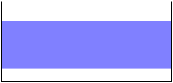
In SVG the origin is in the upper left corner of the canvas. Changing the height of an object results in the top of the object being fixed, and the bottom of the object being closer to or farther away from that top. What we want in this case, is to have the bottom of the object fixed, and the top of the object being closer to or farther away from the top, depending on the height of the object.
SVG image (revisited)
A naive solution would be to add a second output mapping, to correct the vertical position (y attribute) of the water rectangle. This is a valid solution, and it works. There is however a simpler and more elegant solution.
Consider the following, updated SVG image:
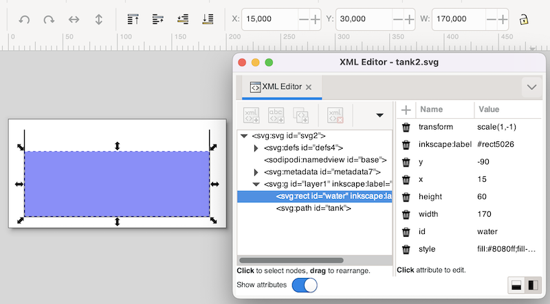
This SVG image is the same as the original SVG image for this example, but with an inverted y-axis, for the water rectangle. The y-axis was inverted by using the Flip Vertical command from Inkscape’s Object menu, while the water rectangle was selected. As can be seen in the screenshot, Inkscape corrects for the applied transformation, and still indicates the same x and y coordinates (at the top of the screenshot). In SVG (and thus the XML Editor window), we see a new transform attribute, scale(1,-1) as value, which represents the inversion of the y-axis. Also, the bottom of the water (the inverted top of the water) is now 90 pixels (the inverted -90 value of the y attribute) from the top of the image. Using this vertical flip, we now fixated the 'bottom' of the water, and we can thus change the height of the water without having to correct its position. The mappings for this modified SVG image are the same as the original mappings.